 Welcome at my tenth V8-update! :)
Time flies: the previous update dated April 2017, almost a year and a half ago. Of course I’ve been busy — I always am — you’ll see that in this report.
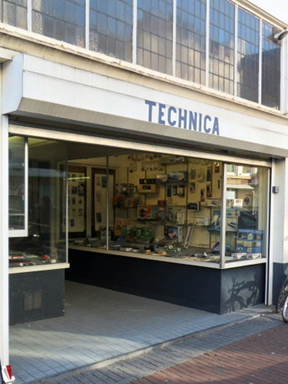
On March 31, 2017 I visited Technica, Nijmegens world famous electronics store. For more than thirty years I’ve scored everything involving lights and circuits there.
 Technica is owned by Marc van Blijderveen, an enthusiastic and highly skilled electronics expert. I talked to him about developing a warning system for my water-methanol injection: because the liquid is in the closed swingarm, I can not check its level. And too low a level is not desirable (read: dangerous) because if the engine expects water-methanol and it doesn’t get it injected, the engine can be badly damaged in a matter of seconds.
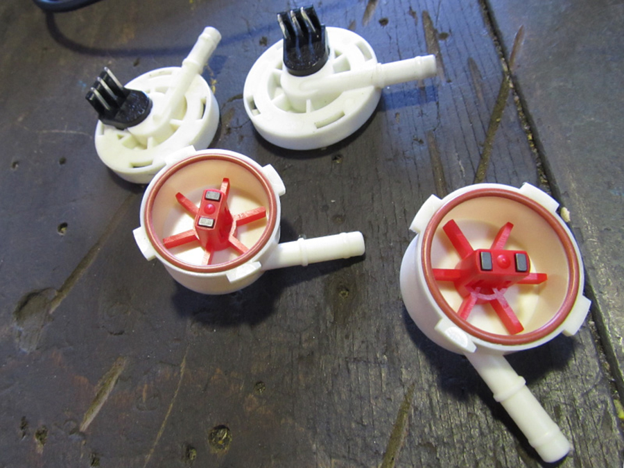
 Marc suggested using two flow sensors. These are impeller wheels that can register fluid quantities by means of pulses, similar to the ‘petrol mills’ that you might remember from petrol stations. Except these are much smaller, and come from coffee makers.
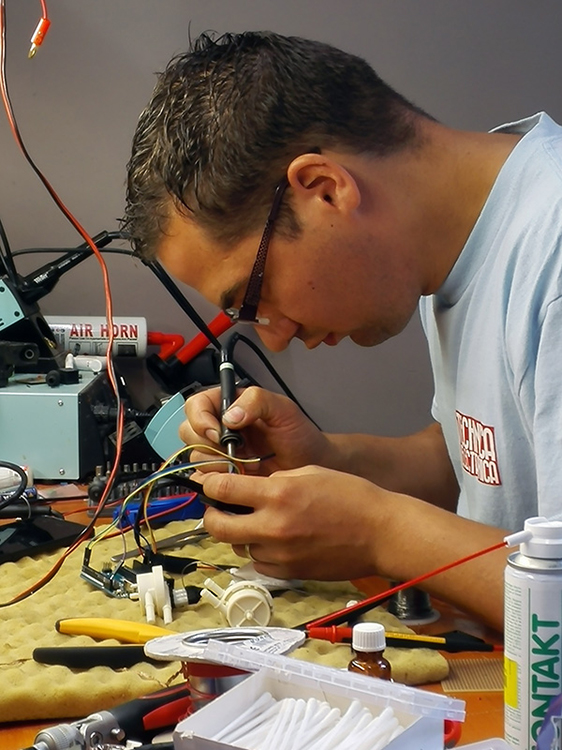
 Marc developed an electronic circuit based on the Arduino Mini, with an external LED switch with which you can both configure and reset the counter.

In addition to the hardware, Marc had to do some serious programming work too.
 Sophisticated and small, this circuit.
 The first test results were not unambiguously positive. At the end of August Marc came to the ‘scene of the crime’ to determine the cause.
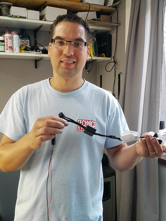
The flow sensors turned out to be defective. After they were replaced …

… Marc improved the software a bit and the test was successful.
The system now works as follows: the two flow sensors count the pulses and thus the amount of water-methanol leaving the swingarm. Once 80% of the total volume has been counted, the Arduino gives a signal to the engine management that the liquid level is low. At that moment, testing (or riding) must stop and the system must be refilled.

Check check double check: both nozzles give a beautiful mist, and the system warns on time.

In the meantime Peter completed the bike’s wiring, and the indispensable wiring scheme.
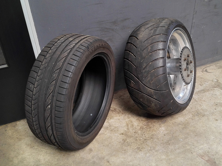
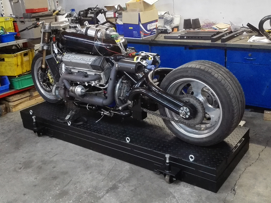
We decided to make testing a bit more safe. We feared the motorcycle tire (r) would fail during testing so I replaced it by a car tire from an Aston Martin DB7 (l), one that can handle high speeds and loads.
The first test day was scheduled for 18 September 2017. The first test with the new engine, a new engine management, new wiring, a new intake manifold, new ignition coils, an improved water methanol system, a different rear tire, more sensors and much more new and improved stuff. Well, see update 9.
However, it would not be a very successful day: only one of the four lambda probes worked and, certainly so impeding …

… the crankshaft was not able to make a complete turn. We suspected that the new crankshaft nuts were just a little longer than the ones from the old engine and thus scratched the oilpan. We peeked in the (still mounted) oilpan with a camera …

… and saw this was the case. No start. Bummer.
 Well okay. And what do you do next? Remove the oilpan completely. But to do that, the frame had to be split and the whole front disassembled. Starting with the happy pink coolant.

Nevertheless, it was a useful meeting because Niels, Peter and I enhanced the engine management, the new sensors and the wiring diagram.
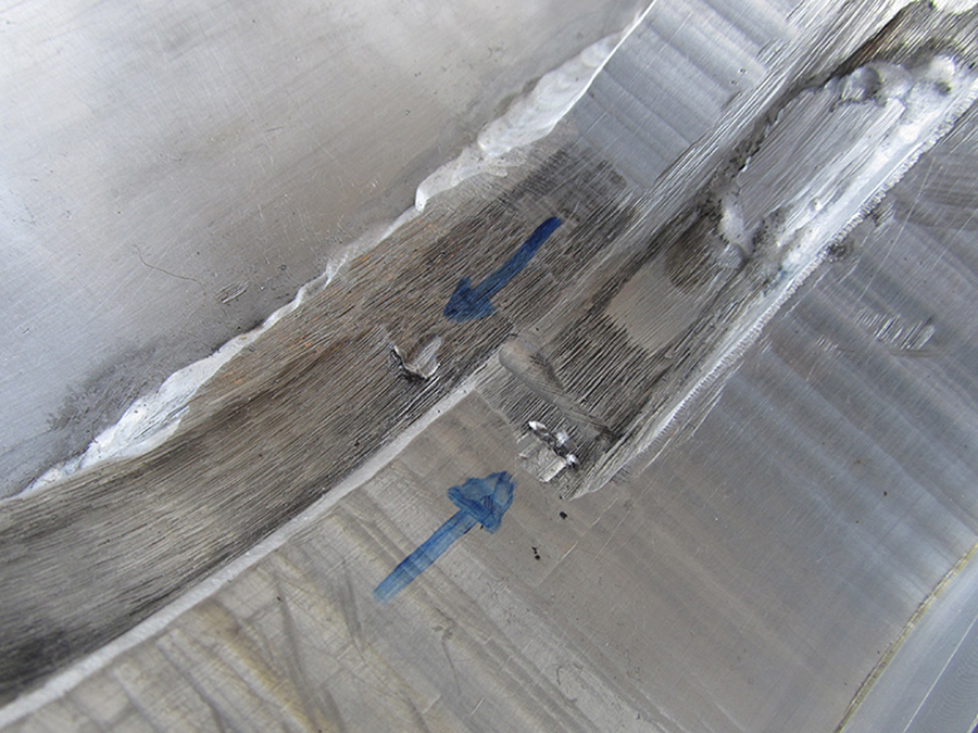
The arrows show where the bolts scratch the oilpan.

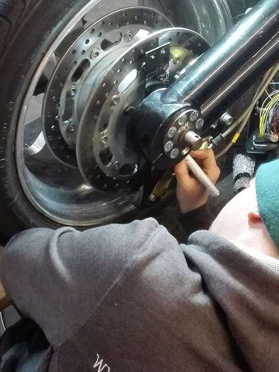
With a try square, a ruler and a pair of grip wrenches I constructed a system to determine the wall thickness of the oilpan …
 … to ensure that I would remove just the right amount of alloy.
 And while I was at it, I made an indicator for the ignition timing; it points at the degree indication on the balancer.
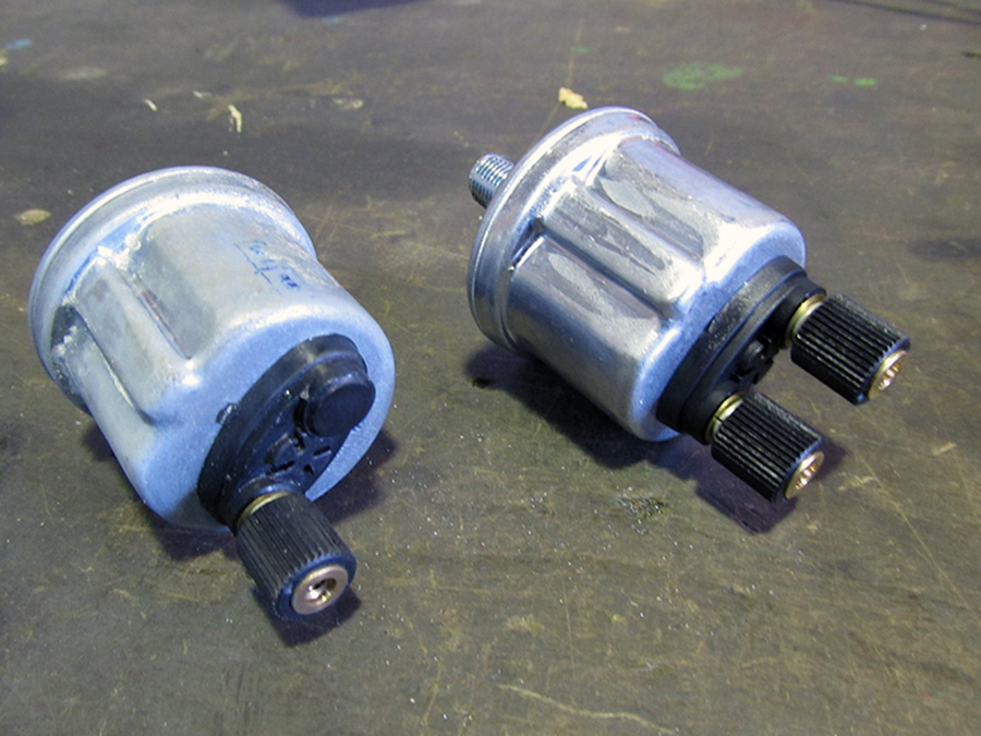
October 19, 2017: test day! Determining TDC (Top Dead Center) took quite some time but most of the time we were configuring the new oil pressure sensor (r). We measured the various values with a multimeter while a compressor and pressure gauge were connected. Then in Excel, Niels made a spreadsheet with 1,024 values that we uploaded in the engine management system. And gone was another day.
October 21, 2017: another test day, two days later. The new engine started right away, and sounded like music.

An engine sound for the first time in twenty months! Peter tuned the ignition timing.
In contrast to the first engine, we had a decent running-in procedure: 20 minutes at 1,700 rpm …
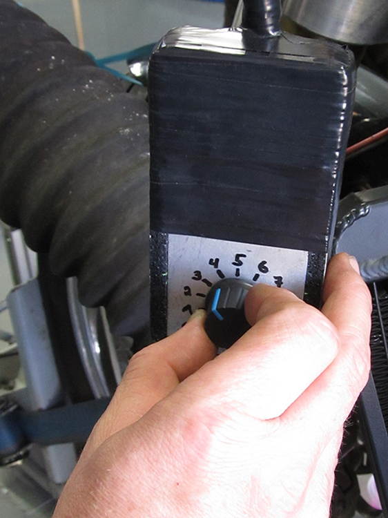 … with light braking to stress the engine a bit. And then the system was tuned to 3,000 rpm, ready for street use.

We took the spark plugs out to check the color: perfect.

Satisfied faces on the 21st October 2017. ;)

In the following weeks Peter shortened the unnecessarily long lambda cables: at the top you see the removed part, at the bottom of the result …
 … and engineer and tractor puller Josef Siebers was asked to strengthen the Dyno bench.
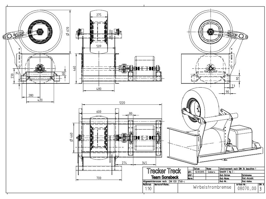
He drew the construction that must prevent the bike from shooting forward during testing and blasting straight through the rear wall of the test room. Such a situation might occur if the front fork breaks due to the forward force of the engine: the rear wheel then moves from the drum on to the static part of the bench, with disastrous consequences.
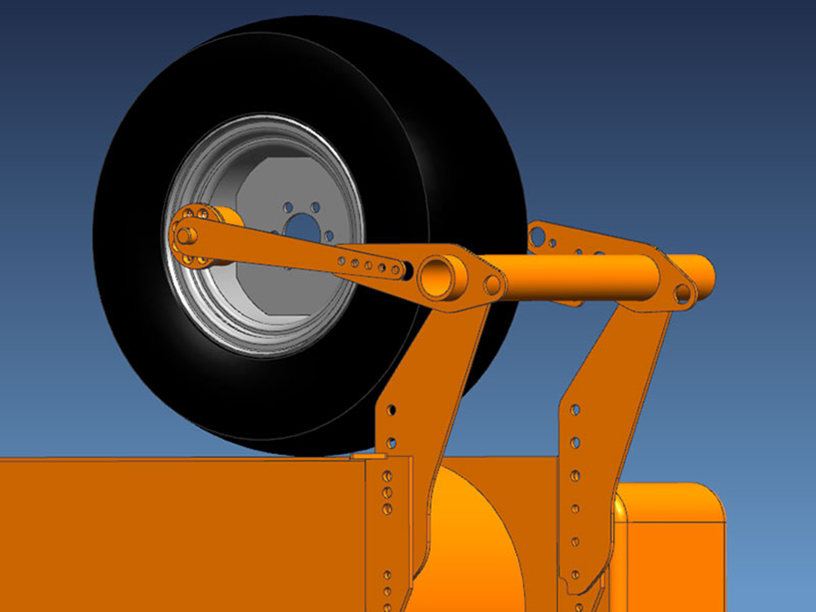
The construction is adjustable over all three axles, so that it can also be used for other motorcycles.
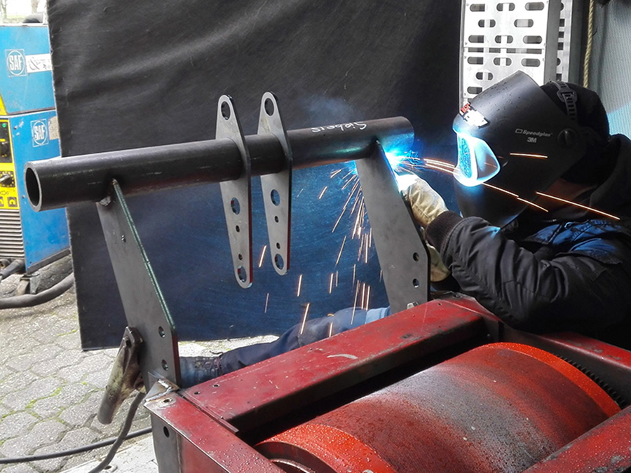
Peter welded the static parts on the back of the test bench.
 On February 21, 2018 was the next test day. I bolted heavy disks on the chain tensioners …

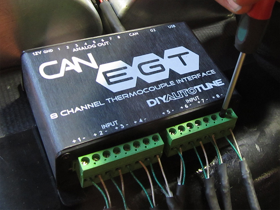
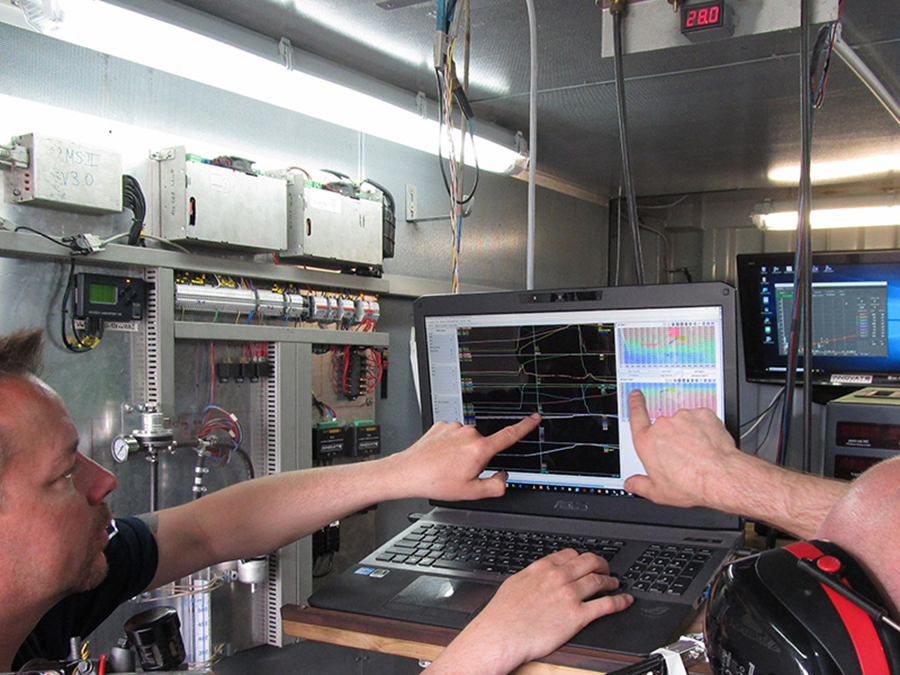
A so-called CAN EGT module was attached to the tank: it communicated with the engine management system and the eight EGT sensors. They measure the temperature of the exhaust gases in each cylinder. This provides a lot of useful (necessary …) information about the fuel-air mixture.


… who passed on his data to a screen during testing. The aim is to keep the colored dots (which represent knocking) under the orange line.
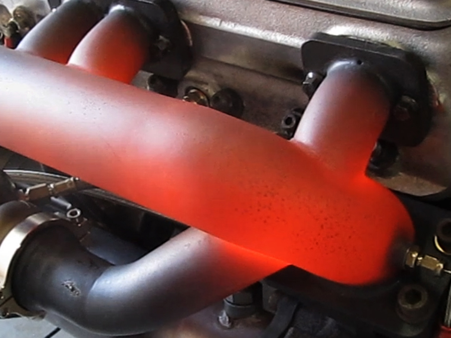
 Zoals gezegd: de motor kon niet meer naar voren maar blijkbaar nog wel naar boven: zie het glimmende oppervlakte van de band. De motor accelereerde zo snel dat de band te weinig grip had op de rol van de testbank. Daardoor maten we slechts 250pk aan het achterwiel. Ook de hoge temperatuur van de band bevestigde ons vermoeden. Werk aan de winkel.
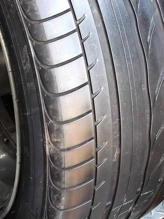
 As said: the engine could not move forward but apparently still upwards: see the shiny surface of the tire. The engine accelerated so fast that the tire did not have enough grip on the test bench’s drum. As a result, we only measured 250hp at the rear wheel. The high temperature of the tire also confirmed our suspicion. There’s work to be done.

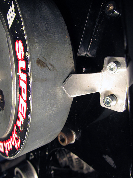
The bike is not only forbidden to move forward (see construction) but also not upwards …
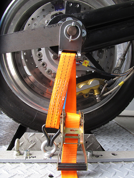 … thus I made is two brackets to pull the rear wheel onto the drum with heavy ratchet straps.
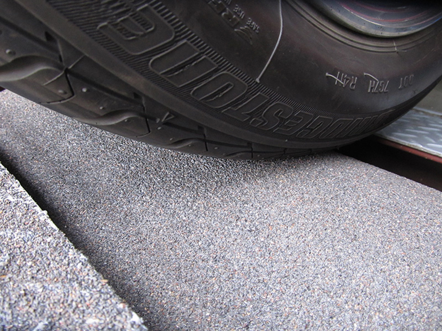
Meanwhile Peter considerably increased the grip of the drum by coating it with a special type of gravel.

The combination of ratchet straps and gravel coating paid off during the test day on March 30, 2018: the sensors did not indicate any wheel slip, which is clearly shown in the roughness of the tire. Fortunately, there was no clutch slip either. Mission accomplished.
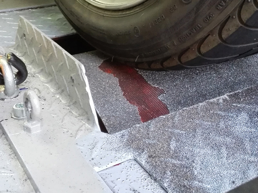
The downward pressure was so high that part of the coating couldn’t withstand.

Furthermore, the familiar course of events: testing, reviewing the datalogs, fine-tuning, and testing again.

Everything remained intact, and we progressed step by step. We deserved the beers.

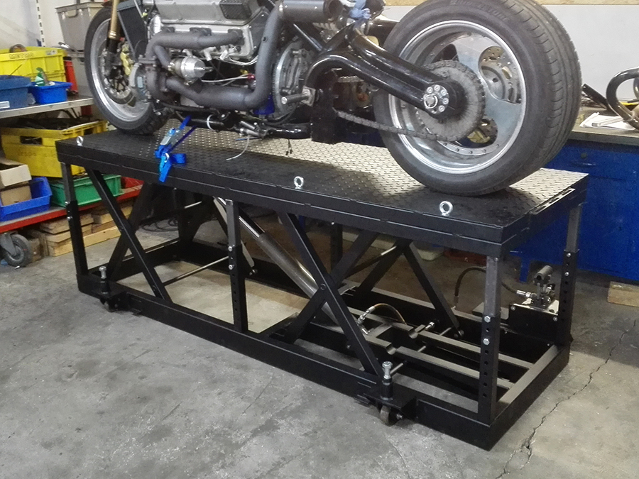
Als intermezzo heb ik in de wintermaanden een hydraulische hefbrug gebouwd. Ik besloot er zelf een te bouwen omdat een fatsoenlijke hefbrug die zware motoren als de mijne (530+ kg) kan tillen rond de 2.000 Euro kost. Voor dat geld bouw ik er zelf een. En dat is natuurlijk ook veel leuker.
Dus concepten bekeken op internet, en uiteindelijk zelf een brug met dubbele schaar ontworpen.
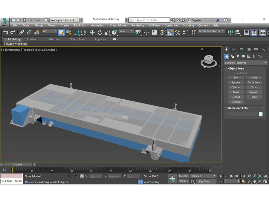
In the lowest position the lift is only 20cm high. And movable with four heavy steel swivel wheels.
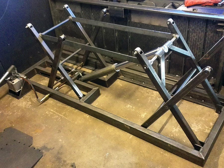
Marking, shortening, lathing, milling and welding.
I have not cut down on strength nor on weight: the hydraulic cylinder alone weighs more than 23 kg, has an extendable rod with a diameter of 60 mm and a stroke of 550 mm. And can push away no less than 6.9 tons.

Here you see the hydraulic hand pump. More robust than an electric one, and significantly cheaper. I’ve integrated a quick release coupling so the pump system can be completely disassembled after the table has been raised to height.
 Many ‘normal’ vehicle lifts use teflon sliders. I am more of real-bearings-and steel-wheels type.

Indestructible..

To relieve the hydraulic system, I made six stanchions with six inner legs, which can be adjusted to height using steel pins. I also made the swivel wheels myself.
For the first test I used curbs and concrete tiles, to see the power of the lift. That went smoothly. See video.
Here you can also see the roller system: first I lift the system with a crowbar, and then I turn a bolt to lower the swivel wheel.

I then had all parts sandblasted and powder coated at Teuwsen in Kranenburg. Great job for a good price.
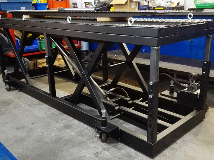
The lift at full height, with the six legs to relieve the hydraulics.
 I made a special ramp, reinforced with heavy channel sections at the bottom.
Bike on top …
… and lifted almost effortless. Ratchet straps on, check.

May 12: test day! Heavy packed and ready to Peter: tools and parts in the trunk, 20 liters of Shell Racing petrol (octane 100) on the side, laptop on the back.
On the left Peter’s youngest son Tim: needless to say on two wheels as well.
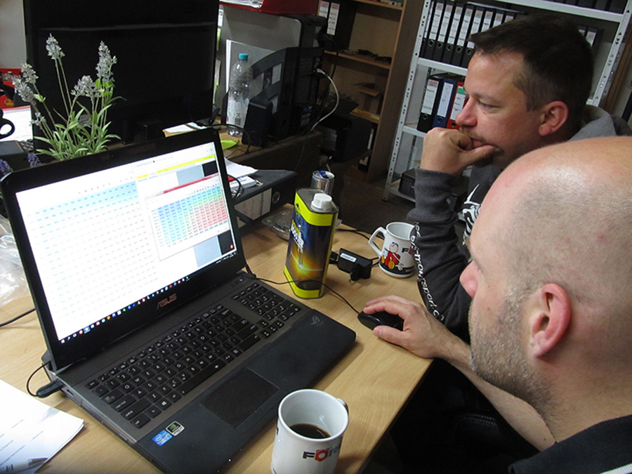
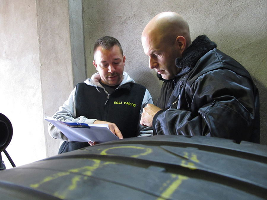
Preliminary meeting with Peter and Niels: discussing the current situation, and determine the order of the upcoming tests.
The ignition was advanced in two-degree steps, and the water-methanol system was used, with varying degrees of success: the cooling function worked fine, unfortunately the Arduino counter did not work. We suspect pollution in the impeller wheels, and I’ll will therefore install filters.

The exhaust manifold leaked, as the black soot shows.
The gasket was torn and unfortunately it could not be removed in one piece. So the entire left exhaust had to be disassembled, and that was quite a time-consuming job, especially because the engine was at operating temperature. As in: hot.
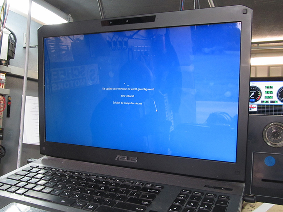
It never rains but it pours: my laptop suddenly started updating Windows 10, and then jammed. Then Peter’s PC started to update Java, and that failed as well.
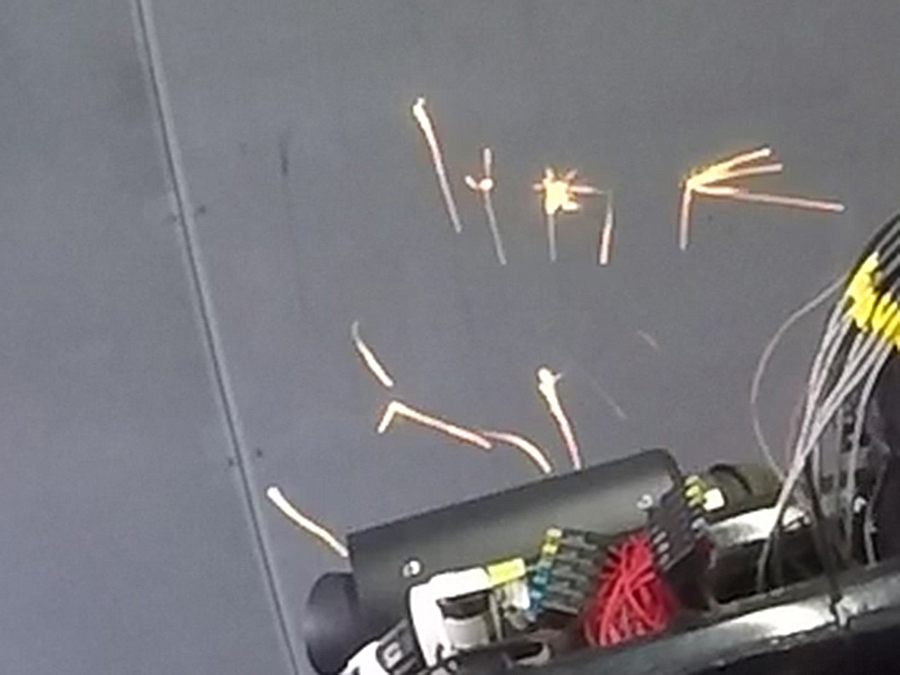
When Peter used the brake during the final test, the day ended in a rain of sparks: something snapped, without a doubt.
The good news that day was the result of the penultimate test: 400.3 hp at the rear wheel @ 537.9 Nm torque and 1.09 bar boost. Broke the 400 hp barrier! :)
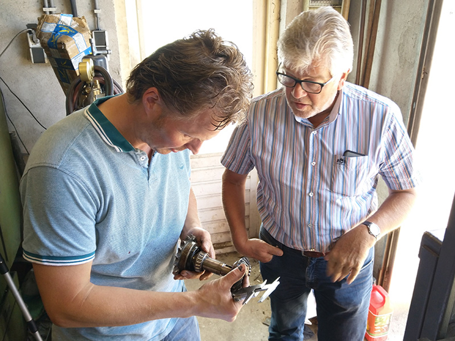
Back to the spark shower: the bevel gear drive, which transfers the power from the engine to the front sprocket via the clutch, broke down. The combination of the engine strength and opposing brake was too much for the device.

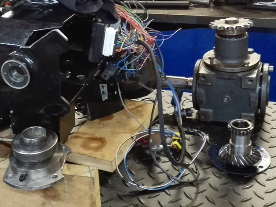
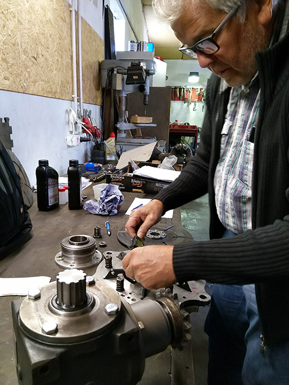
So I took the the rear wheel out, removed the swingarm as well, and opened the transmission …
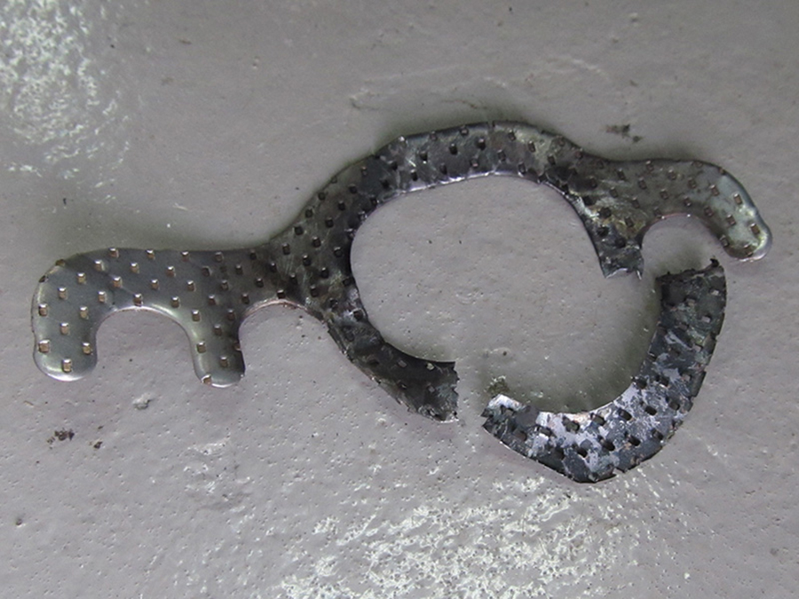
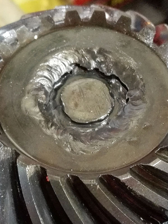 … and note that the weld of a conical gear wheel was broken.
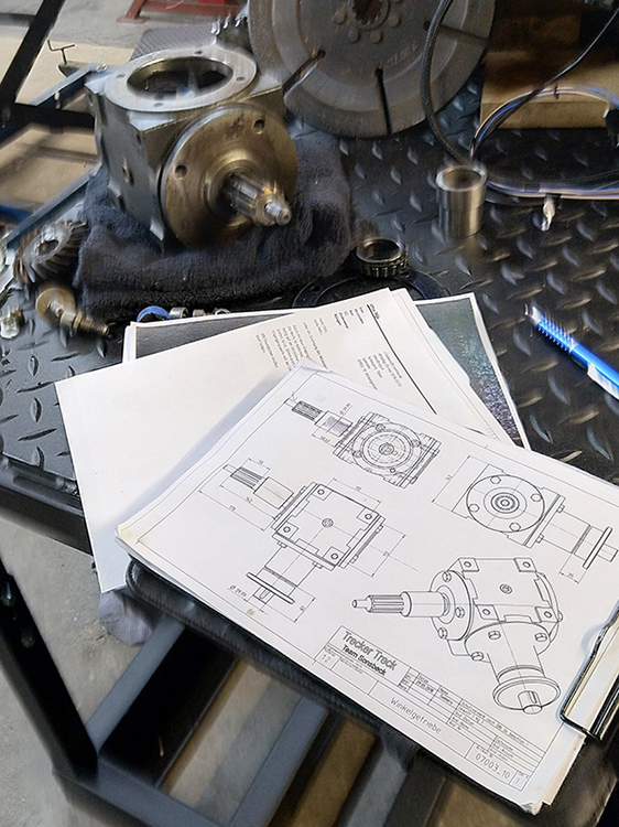 Josef Siebers joined in, thinking about version 2.0 of the transmission, starting with drawing the 1.0 version.
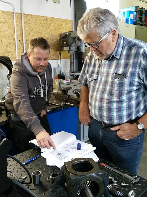 The three of us discussed what the options were.
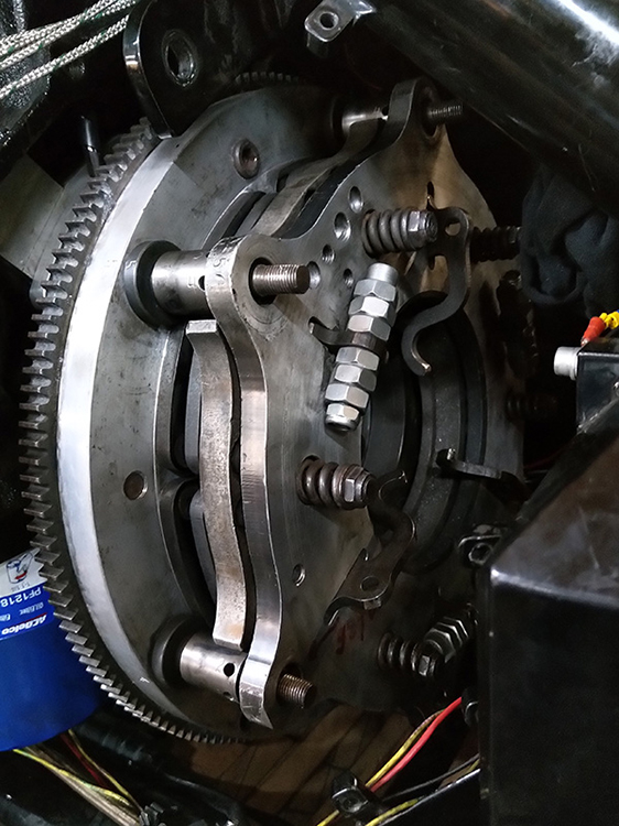 We also reviewed the entire clutch system, ‘while we were at it’ …

… and decided to also overhaul this part.
Josef and I visited Jurriën van de Geer. Jurriën (l) is a specialist in overhauling gearboxes, especially for tractor pulling. He accepted the assignment to renew the inner and outer work of the bevel gear drive and, above all, to strengthen it.

In the meantime I started with updating the clutch. The so-called ‘clutch buttons’ were worn out. The six centrifugal arms press these steel cylinders to engage the clutch.
I lathed the buttons of steel grade C45, which is very tough, and hardened them with fire and oil. In the end I refrained from hardening them because it makes the steel too brittle.
 Furthermore, I discovered that the clutch was bent hollow so the disks weren’t flat on each other, which reduces grip.
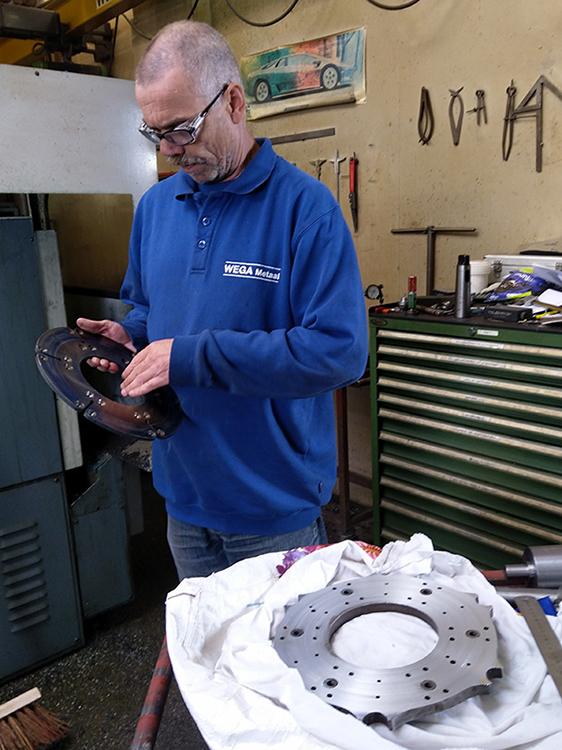 Because my lathe cannot take such big discs, Helmut, from Wega, flattened it for me.
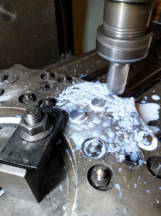 Then I mounted the twelve clutch buttons and flatted them.
 Meanwhile Jurriën sent me pictures of his revision work-in-progress. He owns a so-called ‘wire electrical discharge machine’. With that he cut the heart out of both bevel gears so they can be slid onto a splined shaft, which, of course, is a much stronger solution than a single weld.
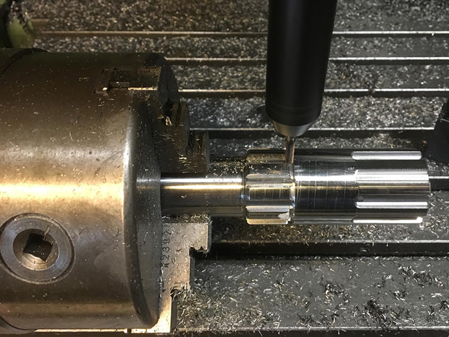
He made the shafts from 34CrNiMo6, and milled splines.
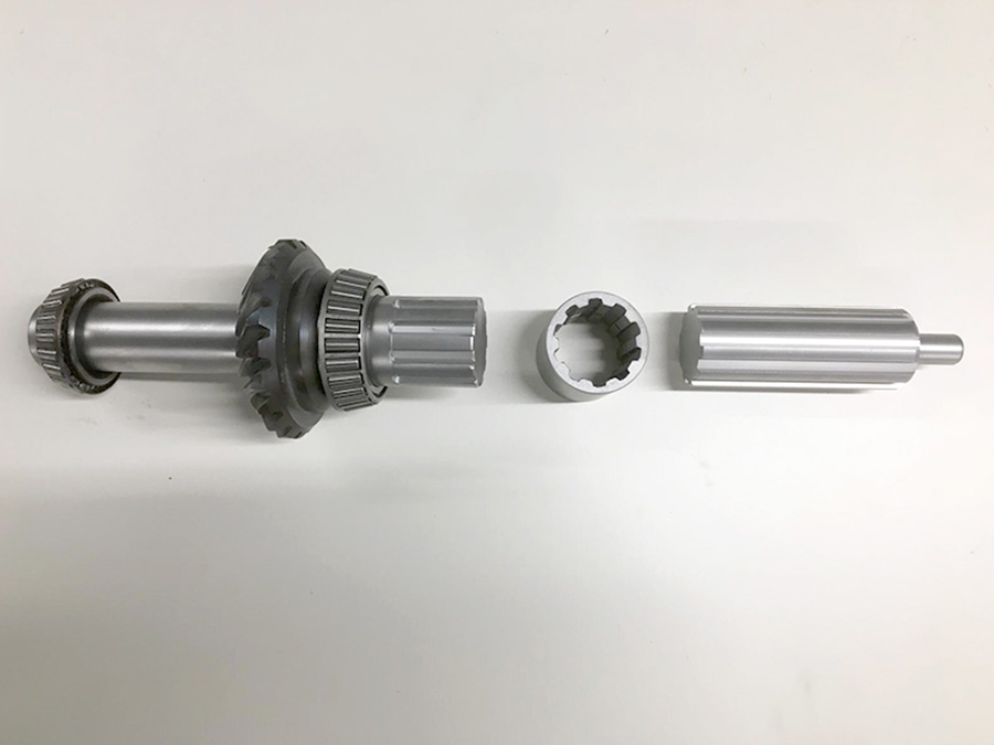
The shaft that goes into the engine (r) consists of two parts with a toothed sleeve over it, thus creating some clearance between the engine and the transmission. This sleeve is made of Toolox44, a very strong and tough type of steel.
 On September 12th I picked up the parts in Overberg, the small town Jurriën lives.
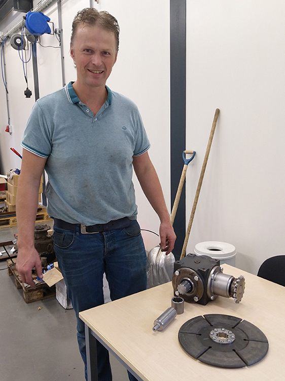 Here he’s posing next to his creations. An enthusiastic craftsman.
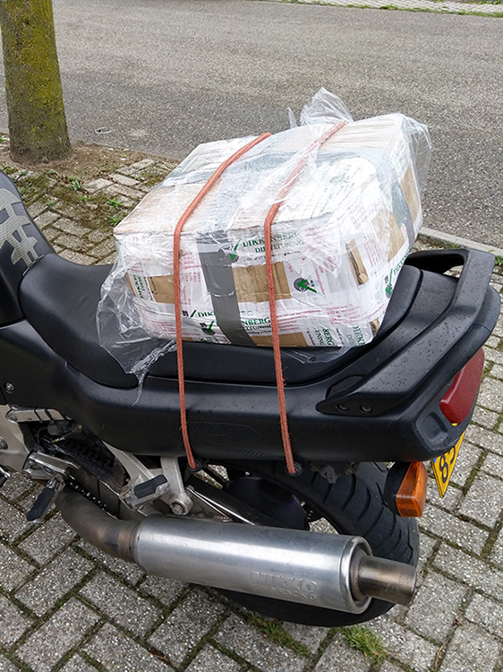 32 kilos of steel strapped on the GSX-R, back home, in the pouring rain. Never a dull moment. ;)

Jurriën also renewed an external part of the gear drive as it was unfortunately ruined while dismantling.
 The kit: two spline shafts, sleeve, transmission.
 Also the heart of the clutch disc was replaced, and broadened …

… to limit wear on the shaft; see the original shaft (r).
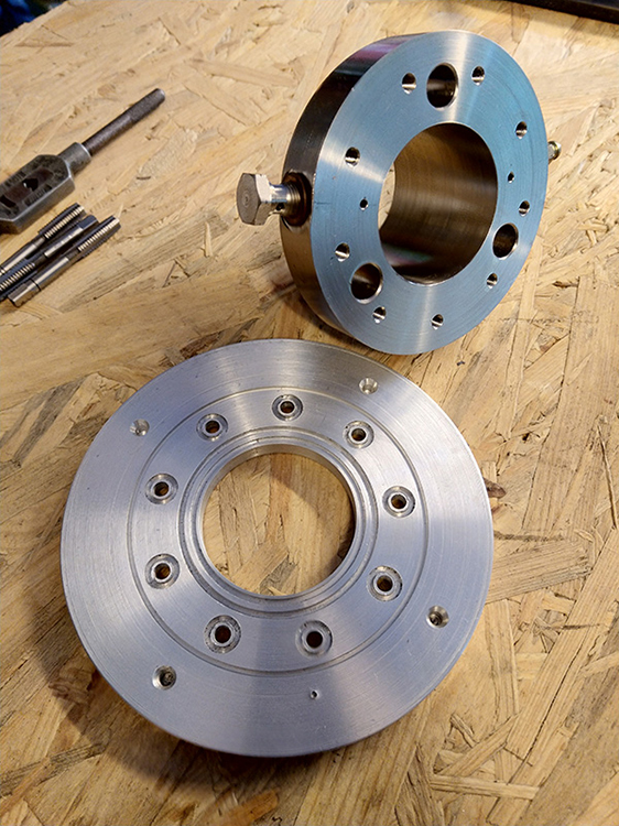
 The sleeve around the new shaft created a new problem new challenge: the inner diameter of the hydraulic pressure group proved to be too small.
 Fortunately Josef had a pressure bearing that was bigger than my current one, so based on that …
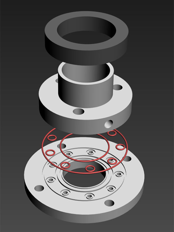 … I designed a new pressure group.
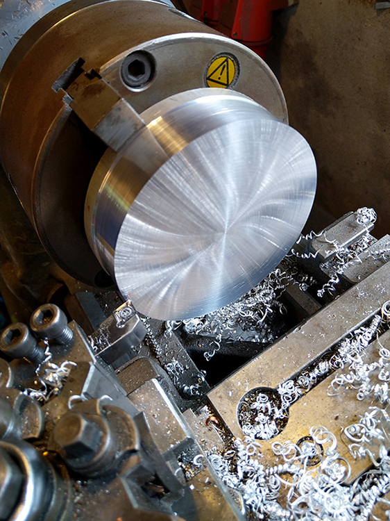 From coarse …
 … to fine. Almost nothing as fun as working on the lathe.
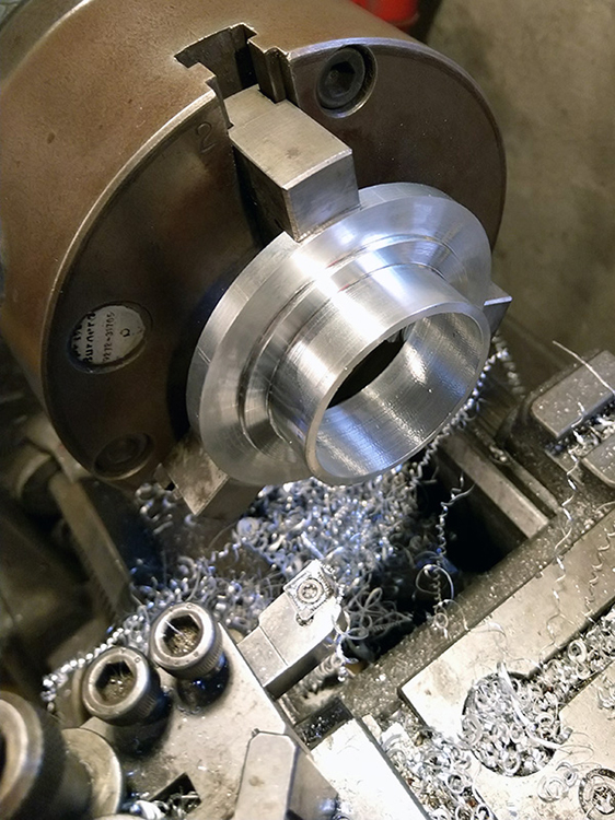
 Lathing a notch …
 … for a circlip that limits the stroke of the pressure group.
 Notches for the o-rings. Courtesy of René Peters at Eriks Arnhem for technical support.

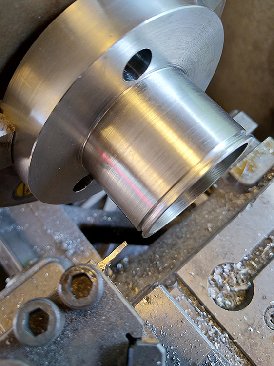
Precision work: I made the three 12mm pistons from hard chrome axle, for holes with an H7 fitting.
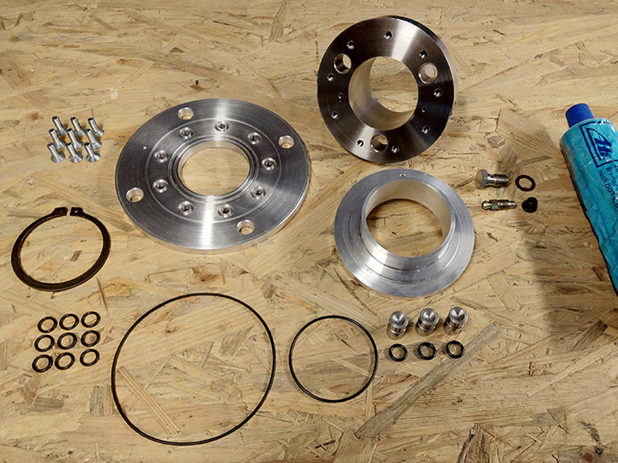
The complete kit of the new hydraulic pressure group. Surgical accurate.
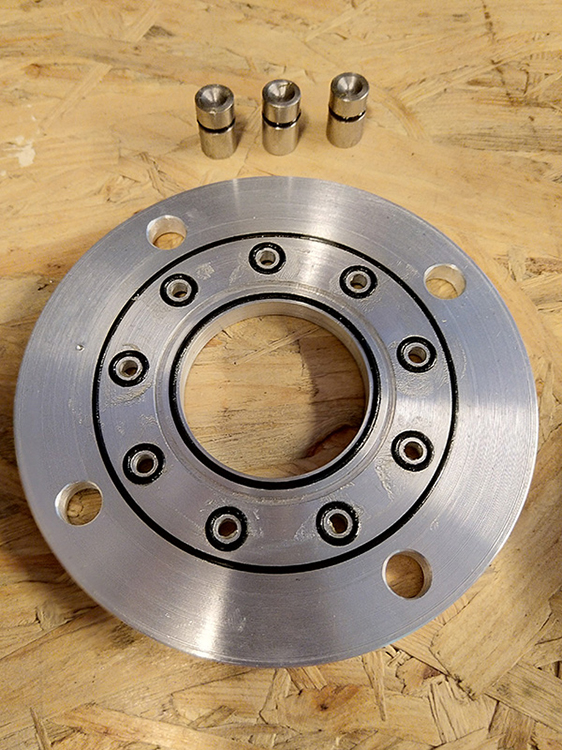 Fitting the o-rings …
… et voilá!
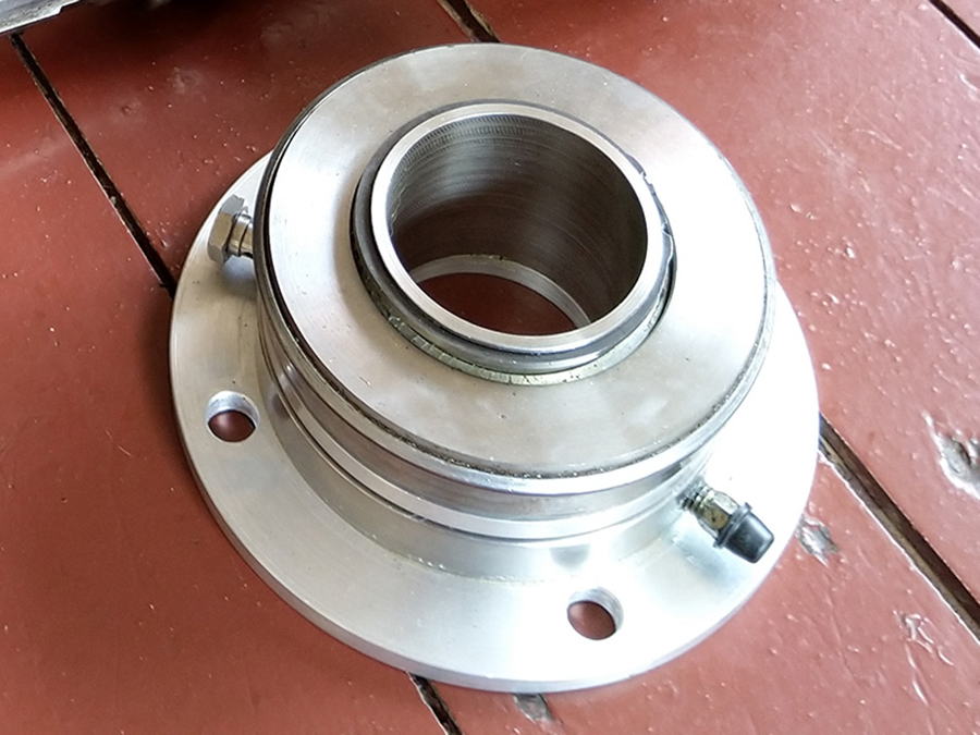
Test set-up, with clutch springs.
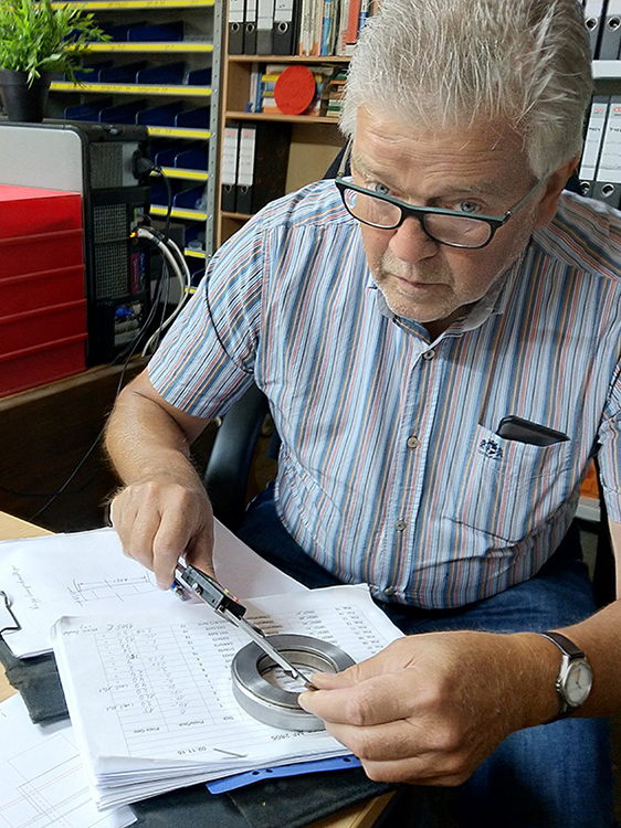
 In the meantime, Joseph took care of the new centrifugal arms. Because yes, those too have to be renewed as well, because of the larger bearing. Measuring …
 … and writing down. And then draw. And then fabricate. And then assemble. And then test. And then be satisfied. Or not being satisfied and improve. And test. Trial and error to the bitter end. It’s the story of this project.
First steps: install, test and adjust the clutch and the transmission. Then continue tuning for more horsepower and torque.
In short: to continue … go here.