 Welcome to update 12, almost three years (!) after the previous one. Main cause of this delay: the corona crisis.
I ended up in update 11 with a rather dangerous backfire. And with the happy observation that we were still alive, and that the engine still was intact, quite important as well.
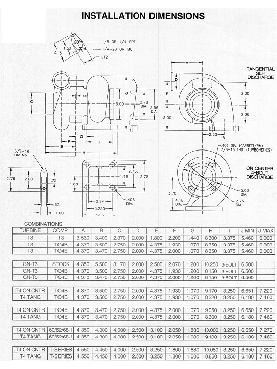
To increase the flow of the exhausts, we looked for larger turbine housings for the turbos.
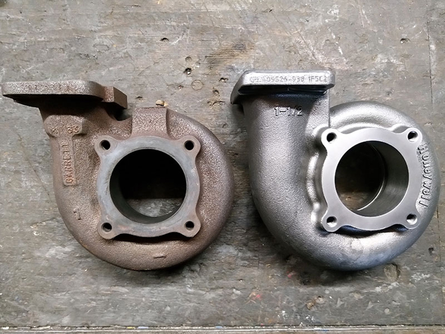
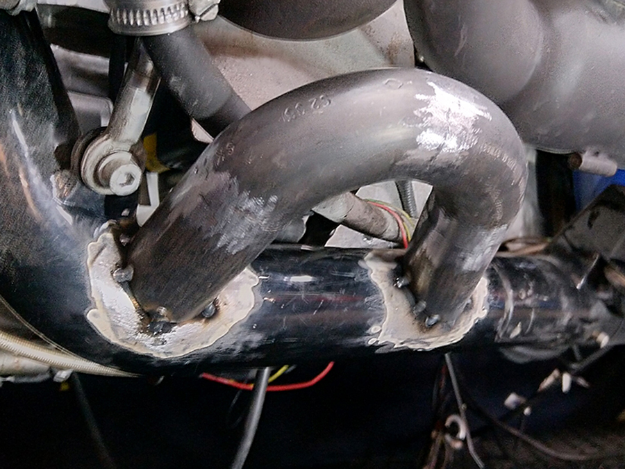
Both turbine housings (left) have been enlarged from .63 to .82 A/R (right). The larger passage causes greater flow and therefore less pressure in the exhaust manifold.
 A minor cosmetic adjustment was required to make the turbine housings fit the exhaust manifolds: an hour and a half of painstaking clamping, then five minutes of milling.

Optically no difference with the smaller turbines. But because a turbocharged engine is no more than just the right amount of gasoline mixed with just the right amount of compressed air, its size matters.
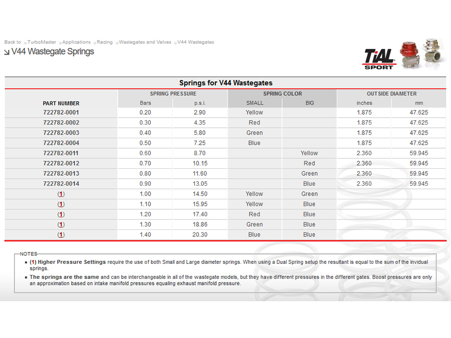
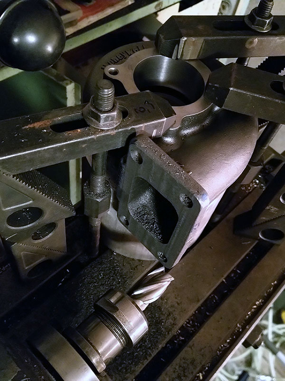
Speaking of ‘air’: the wastegates, in combination with an electric PWM solenoid, regulate the pressure in the intake manifold. We decided to replace the 0.2 bar springs with 0.5 bar springs.
 On the left the narrow 0.2 bar spring, replaced by the narrow 0.5 bar spring on the right.
To be able to test even better, I also ordered two wide 0.9 bar springs. Combining wide and narrow springs allows us to test different wastegate configurations:
0.2 bar: yellow narrow;
0.5 bar: blue narrow;
0.9 bar: blue wide;
1.1 bar: yellow narrow + blue wide;
1.4 bar: blue narrow + blue wide.
And then it was mid-March 2020, and corona struck. Working in Germany was no longer allowed, and the project came to a standstill.
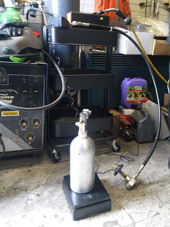 In May, together with Erwin, I took a trip to Marcel from corsa-novatuning.nl, because he could fill my NOS bottle.
 Nice guy, crazy about tuning and sprinting Opel Corsa’s.
 Between the lockdowns, Peter Scheepers and I prepared hardware and software for NOS.
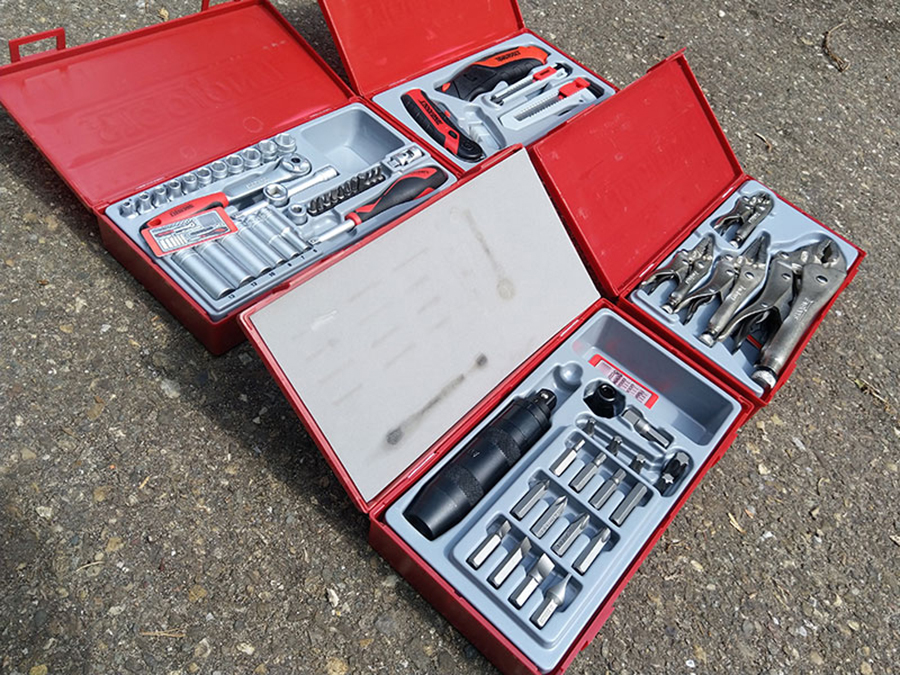
And what do you do with holiday bonus if you cannot go on holiday? Not a difficult choice: buy quality tools, of course. :)
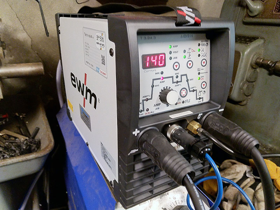
I treated myself to a new TIG welder. A professional one, from EWM.
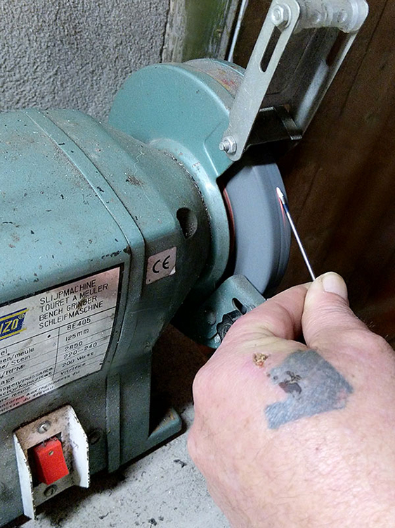 Hans ‘der Dengelmeister’ Eickeler came by one sunny Sunday to teach me some nice TIG tricks. Like sharpening the tungsten electrode at the right angle…

… and guiding welding wire with one hand.
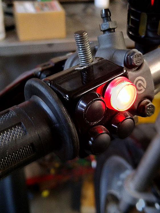
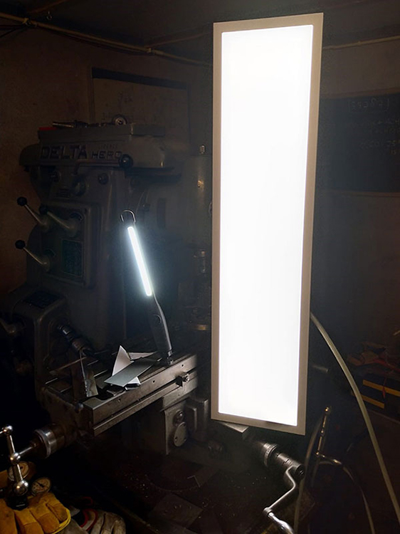 Making beautiful welds wasn’t easy because I couldn’t see what I was doing. I had a good welding helmet so I experimented with additional light sources…
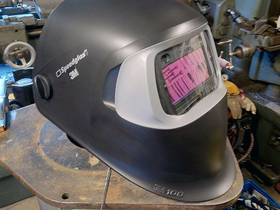
… until I found out that I didn’t have such a good welding helmet after all, and bought me a 3M Speedglas helmet. A world of difference.
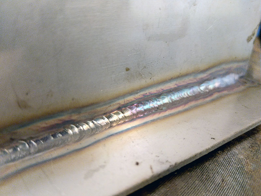
Not perfect yet but we’ll get there.
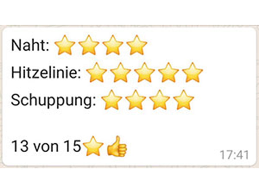
Hans followed his welding student online and awarded stars. ;)
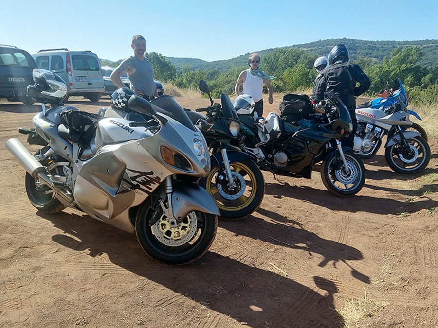
No holiday at all, or…? Between the corona waves, Micky (KTM 990), Walter (CB 500), Joe (self-built), Reinhard (Katana 750), Peter (Katana 1100) and I (Hayabusa) spent two weeks on the winding streets of South France. Great to get away for a while.
 No holiday at all, or…? Between the corona waves, Micky (KTM 990), Walter (CB 500), Joe (self-built), Reinhard (Katana 750), Peter (Katana 1100) and I (Hayabusa) spent two weeks on the winding streets of South France. Great to get away for a while.
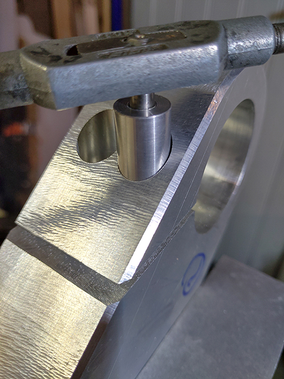
 … after which a bracket was welded against the static part of the Dyno.
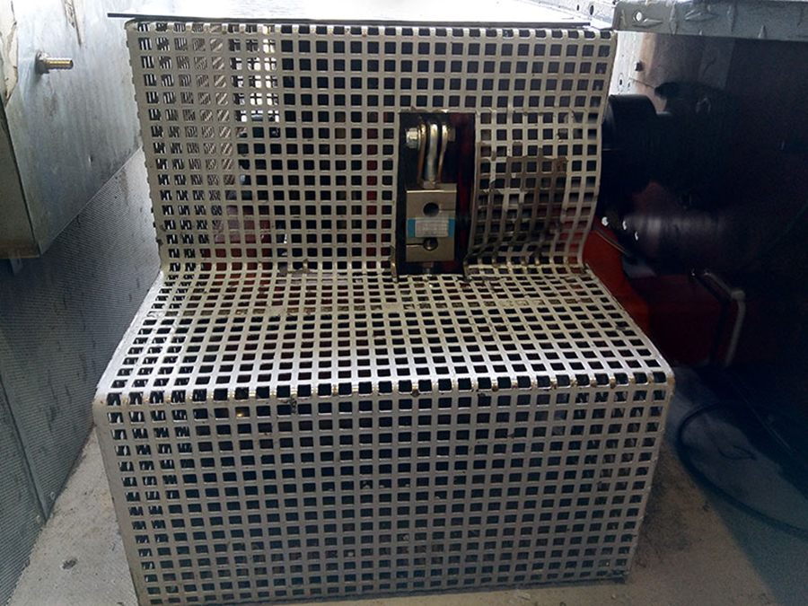
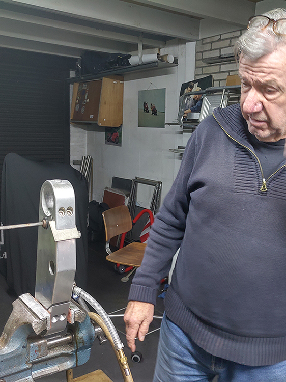
 At the bottom you see the static mounting, in between the measuring bolt (with output cord), connected to the brake. The moment the brake is applied, it pulls on the bolt, and those forces are measured.
The brake is very important to dampen the extreme acceleration of the engine, making it easier to tune.
Putting the hood over it …
 … attaching the measuring unit …

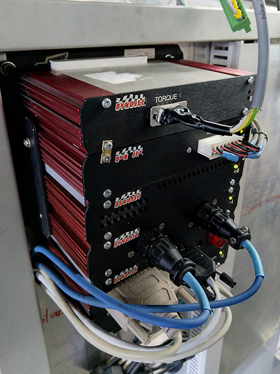
… and the braking output is digitally displayed in Nm, in the middle of the screen.

On January 9, 2021, we hoped for The Last Test: larger turbine housings, stronger wastegate springs, and brake force measurement.
It was another day of brutal violence: flames from the exhaust …
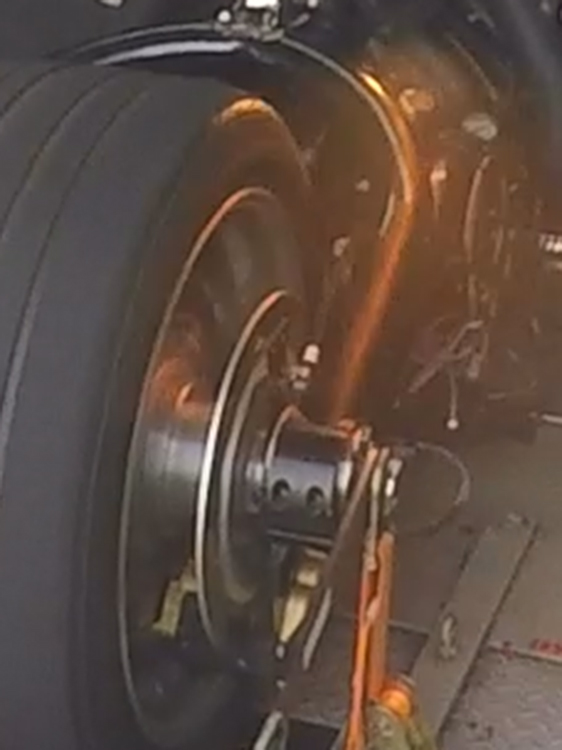 … and an overheated clutch that caused a shower of sparks.
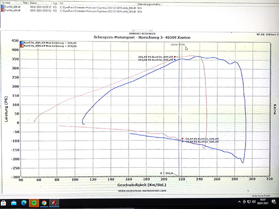
Unfortunately again no chance to go to the max, let alone adding NOS.
And 366 horsepower at the rear wheel, that’s not what we want.
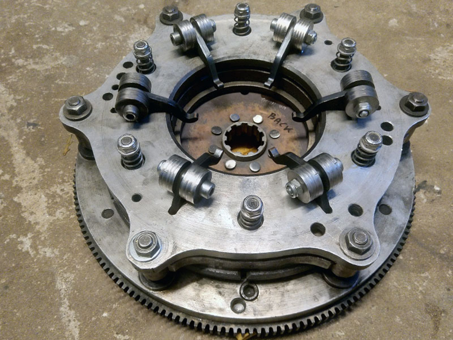
At first we did not understand why the clutch slipped: the centrifugal weights were large: each of the six centrifugal arms had a whopping 110 grams, which should be more than sufficient.
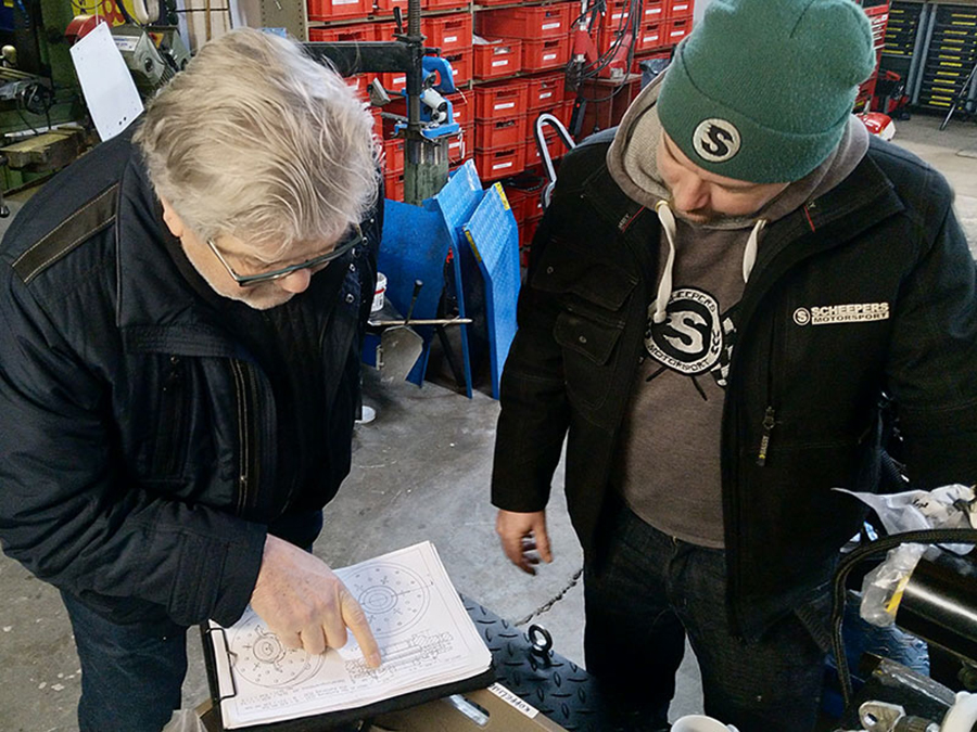
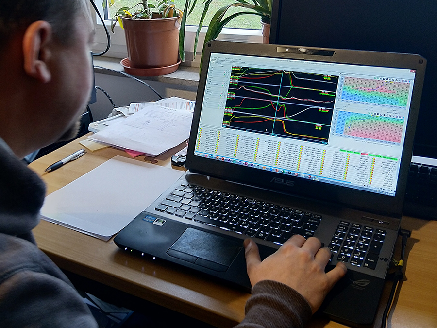
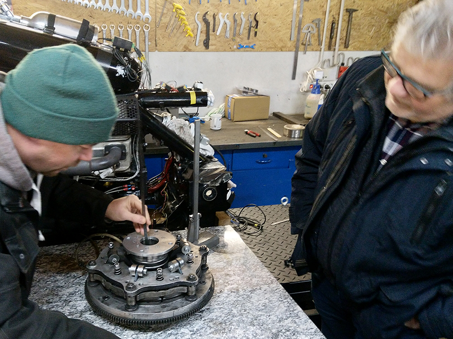
Together with Peter and Josef Siebers we looked for the cause …
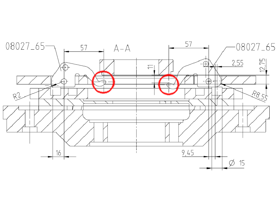
Josef made a new drawing. The left red circle shows the point where the ‘old’ centrifugal arms touch the clutch pressure plate; in the right red circle this point is 4mm lower so that, at higher speed, the arms can rotate enough to really close the clutch.
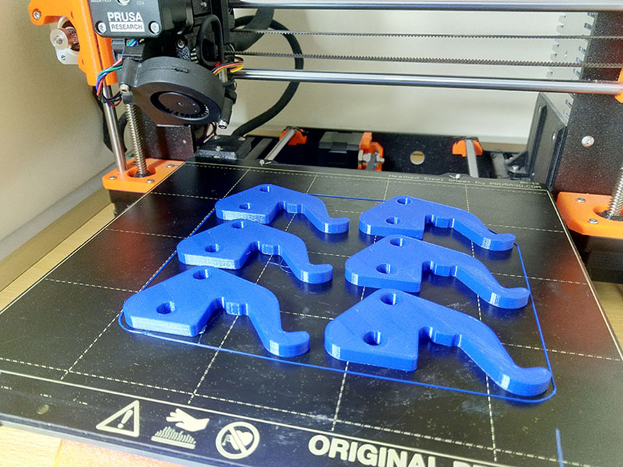
I printed the new designed arms with my 3D printer …

… so that I could check whether there was actually 4mm extra clearance. And that turned out to be the case.
The centrifugal arms were then lasercut in Hardox 500 steel.
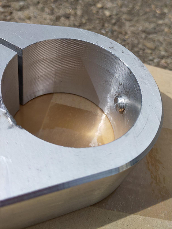
 The shower of sparks during the test on January 19 was caused by the flywheel bending due to the enormous centrifugal forces. This caused the oil pressure sensor nut to chafe and leak oil.
Of course I couldn’t keep it that way.

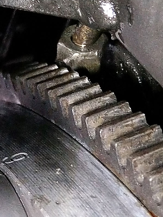
I milled 0.4mm from the back of the starter ring, making it completely flat again.
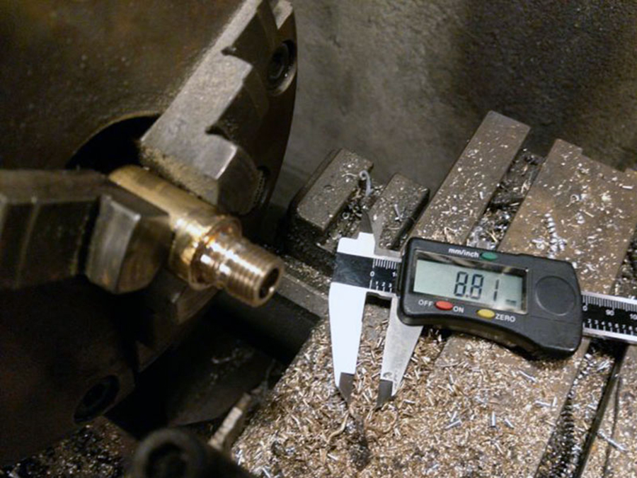
For the new coupler I lathed a bushing, made of brass from 1/4 NPT …

… tapered to 1/8 NPT.
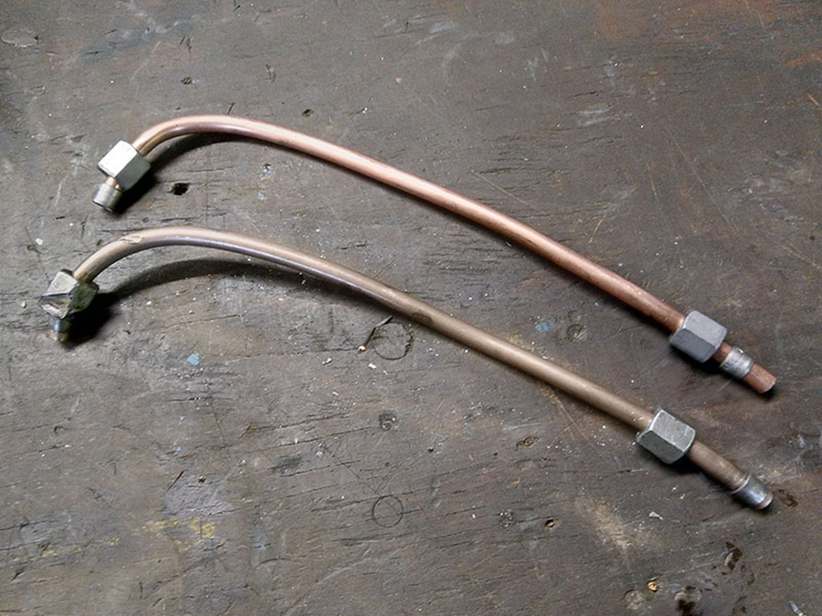
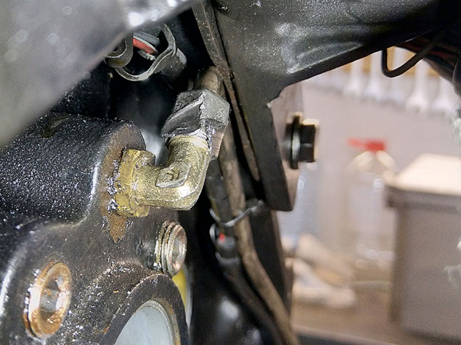
Below the old copper tubing, above the new one.
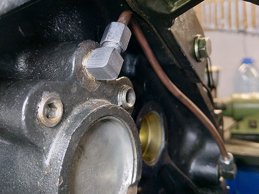
Mounted, now more than two millimeters closer to the engine than the previous one.
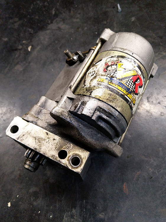 The starter motor had issues so I took care of it right away.
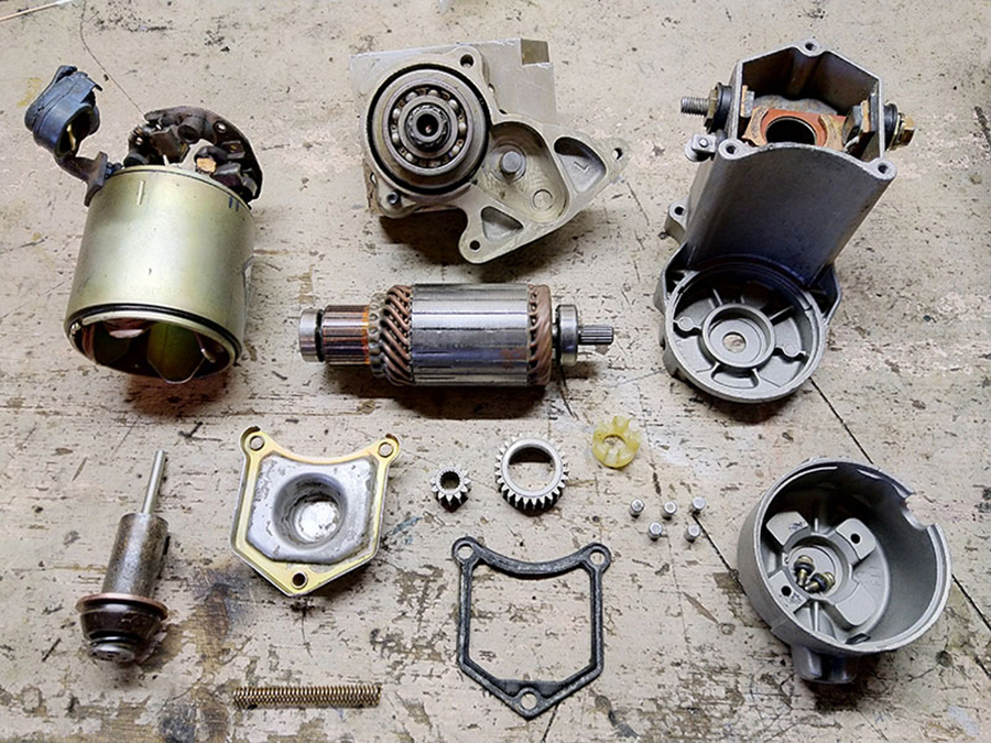
Completely disassembled and yes, that was necessary: the salt, from the second MOT test day on December 9, 2014, had caused quite a bit of corrosion.
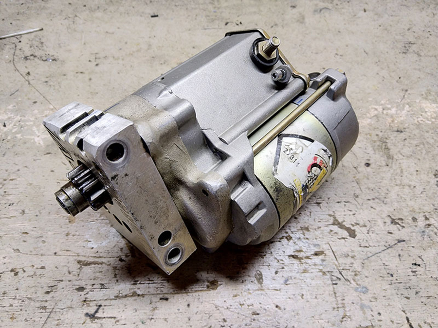
… and it ran like a charm again.
Speaking of ‘running like a charm’: March 31, 2021 was a great day! The new clutch did its job perfectly. Let’s move on to the next stage: adding NOS and boosting the horsepower!

And then, suddenly, there was that Moment of Reflection: will testing ever end, and what if I kill the engine during the test? I want to get on the road, damn it, and drive as long as I can and the law still allows me to. Carpe diem!
Made an important decision: disassemble, paintjob and riding. Tuning after that, as the CBX also had a stage 2 and 3 after the unveiling.
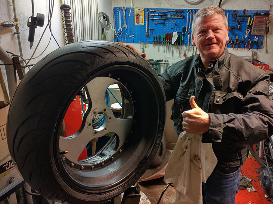
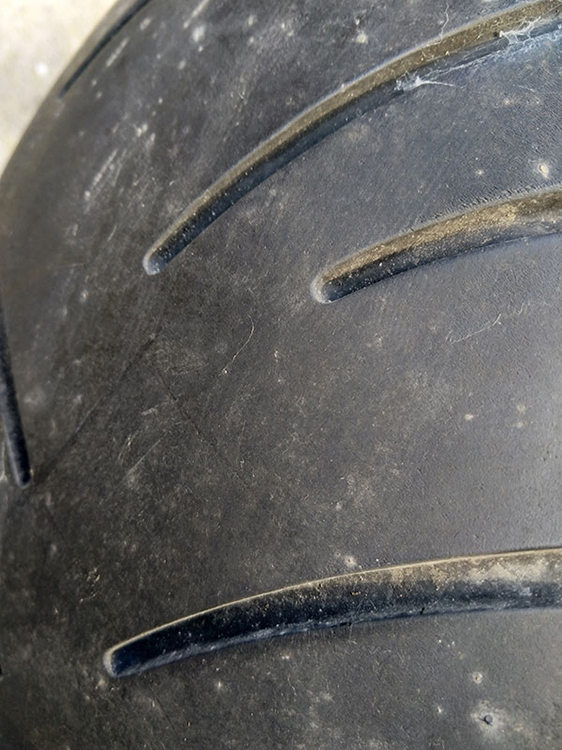 Disassembling: start at the bottom, the tires. Both were still in very good condition of course, because hardly used. On the Dyno I abused a car tyre because it has far more grip (because: flat) than the motorcycle tire.
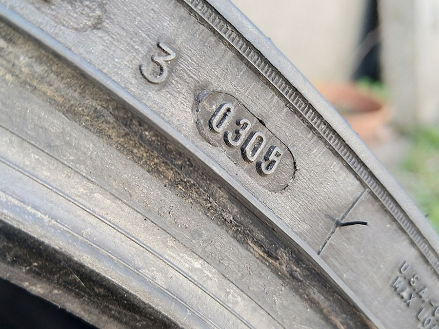
Then why replace it? The code ‘0305’ tells the production date of the tire, which is the third week of 2005. And the rubber of a 17-year-old tire is no longer safe, no matter how good the profile is.
 Mounted an arm and a leg Avon on it, and balanced it just perfectly.
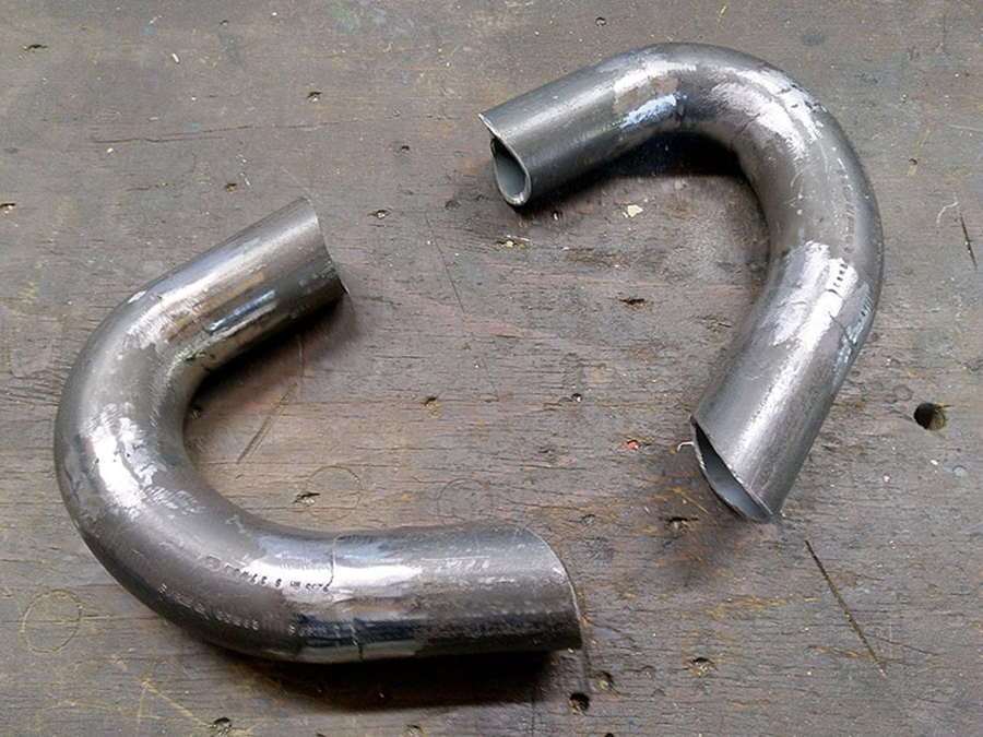
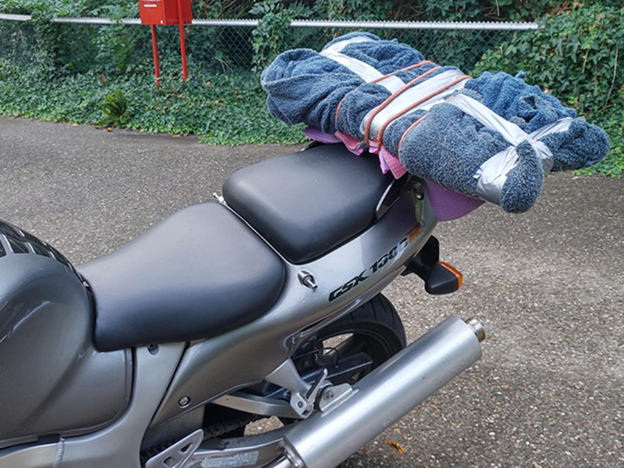
Another wise choice: crash bars. Because if you lose your balance with an bike which weighs more than 500 kilos, you don’t want it to crash on one of the turbos.
Very massive and strong, like the rest.
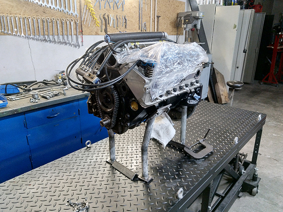
A week later, only the engine was left on the lift bridge. A rather sad sight.
 It was not easy to find a polisher for the many aluminum parts of my bike. I don’t have the hardware to polish properly myself, and I know from experience that it is 1. a craft and 2. makes an incredible mess without proper extraction.
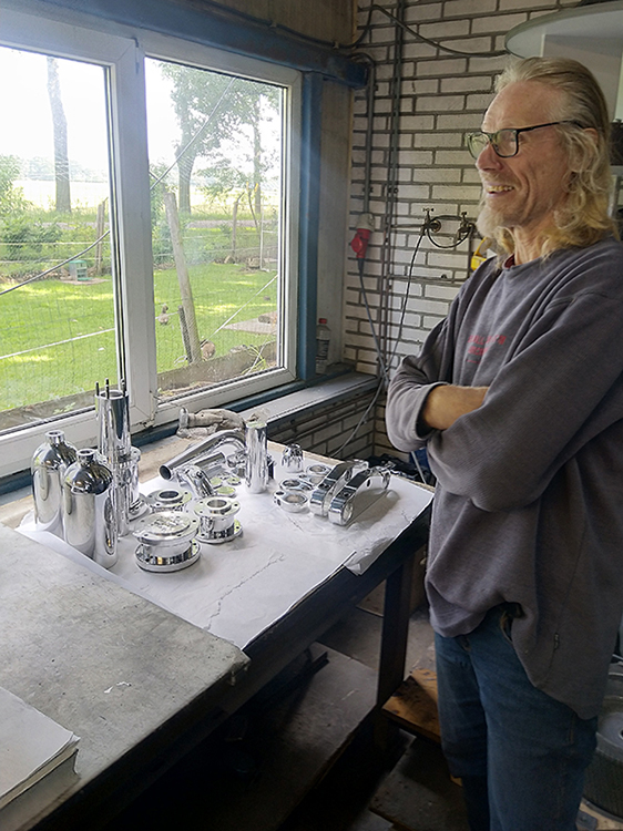
On a beautiful day in June 2021 I took the parts to Roelof van der Velde, owner of polijstbedrijf.com.

After polishing one hardly dared to touch the shiny parts.
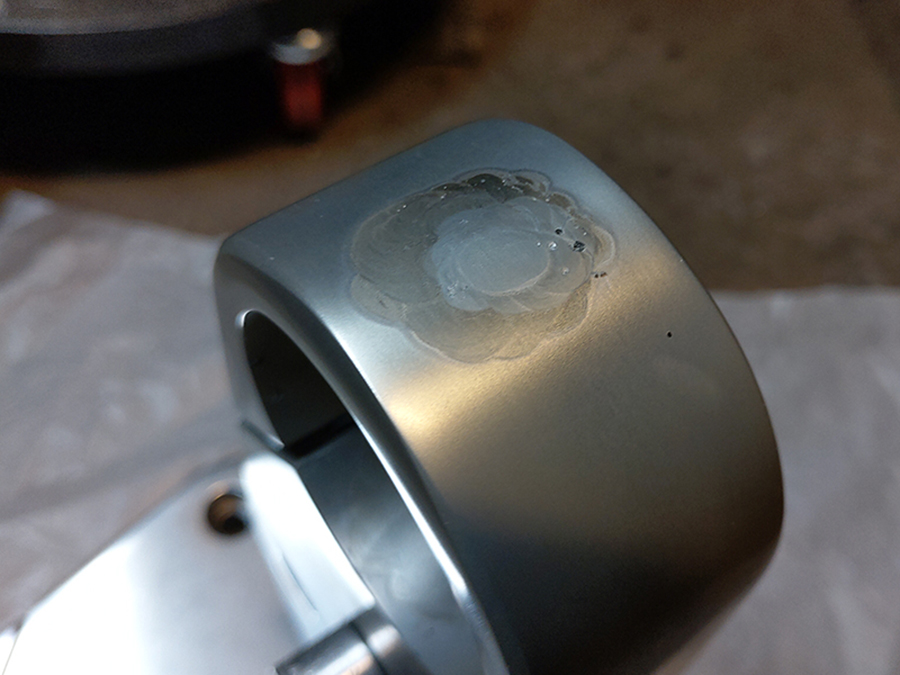
That was the reason I had them anodised immediately: during this electrolytic treatment, a rock-hard layer is created on the aluminum that is not sensitive to weather influences, with a beautiful silky gloss skin.
All was perfect, except for the lower triple tree: the weld spot on the side discolored bad and, even worse, the weld was leaking.
 This caused brake fluid to leak out; this triple tree is used, just like the one on the CBX, as a transit and distributor for the front brake.
The misery that followed was incalculable: three different welders, including master-expert Willy Naves, tried to stop it leaking, but the aluminum had become so hot that it became porous; a lost case. :(
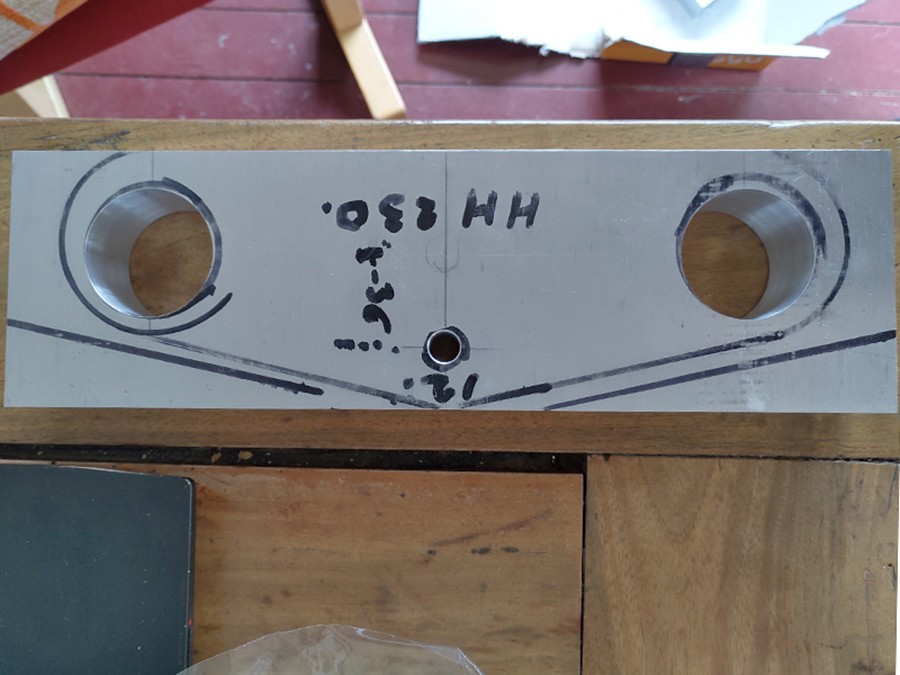
So, gritting my teeth, I had to decide to mill two completely new triple trees.
Quite an exciting adventure on my conventional mill …

… especially when it turned out that it needed major maintenance. That worked out well, many thanks to Niels Saarloos for his advice.
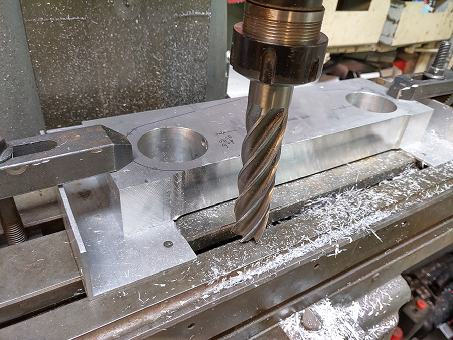
 Milling in a straight line is not a problem on a normal mill like mine, but curves are. I lathed a bush that fit exactly in the front fork opening and bolted it on the milling bed …

… after which I was able to mill the curves with an extended arm. Thanks to Willy Naves for the tip.
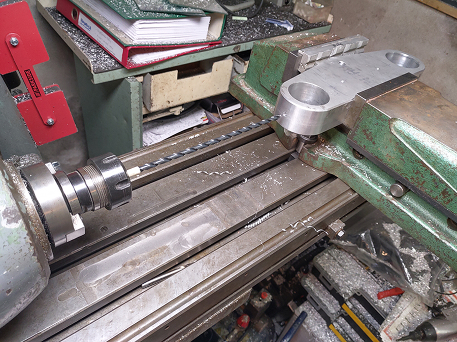
With an extremely long drill I went deep into the triple tree.
With a pounding heart, that is. Because if the drill breaks, the plate ends at the scrapyard, and I can start all over again.
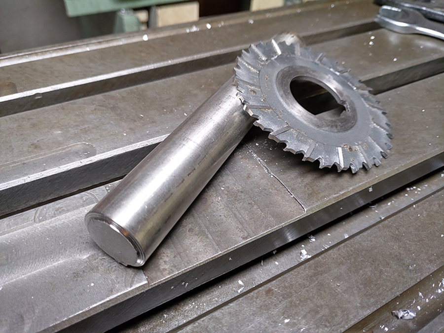
I borrowed a cutting disc from Willy …

… and I lathed a holder for it from a stainless steel rod.

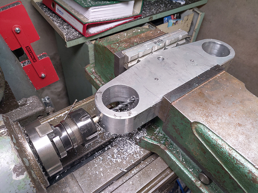
This allowed me to cut slots. Again extremely careful: one snap and it’s all over.

Countersink holes for the bolts.
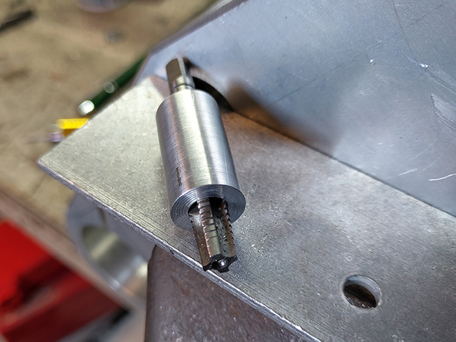
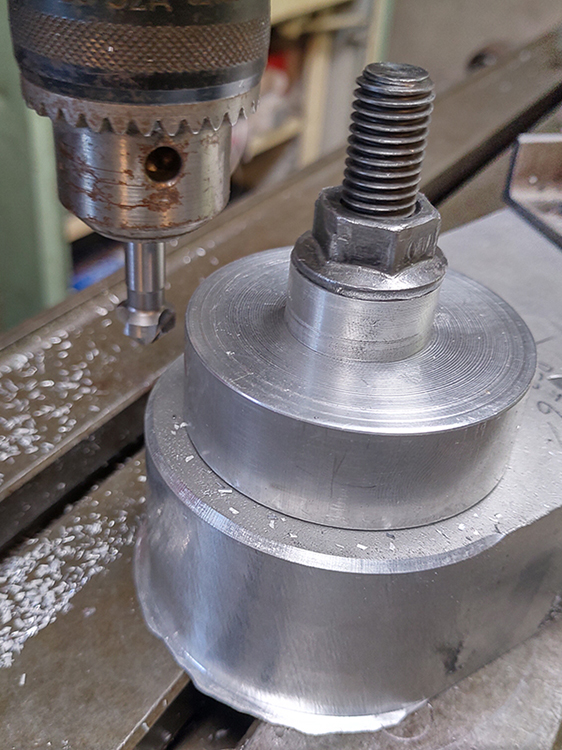
I lathed a guide bush for the threaded tap …
 … which guaranteed a perfectly square thread.
 I capped the holes with a threaded end of exactly the same material as the triple tree: EN AW 6082 T651.
As a result, there was no need for welding; this way I prevented problems with anodising.

In between I pressurized the plate to make sure that the seals were indeed tight.
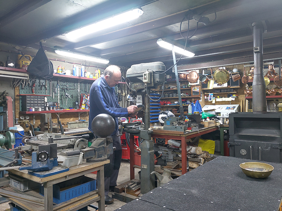
I met 77-year-old Keimpe van Dockum. A great peace emanated from him and his workshop, as if you’d arrived in the 1950s.
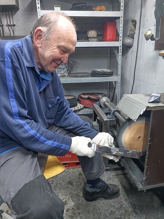 A polishing craftsman.
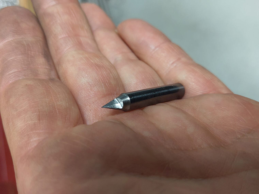
After anodising and pressing again (oiltight! :)), the lower triple tree went to Niels Saarloos who, just like with the previous plate, milled the logo. Here’s the cutter he used …


Windows wouldn’t be Windows if his CNC milling machine’s laptop hadn’t updated while milling. We experienced something like this before, during a Dyno test day. Very annoying.
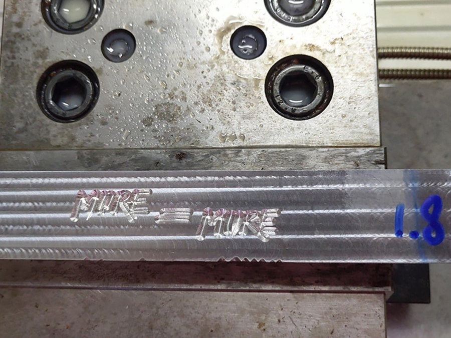
Niels first milled a few experiments to determine the correct depth.
Filming The Real Deal. Again exciting because this phase can also undo all the work.
But: succesfull! :)
Niels also milled the valve covers. These presented him another challenge: the logo not in the covers but on it. This means that all the material around the logo had to be milled away so that the logo remains.
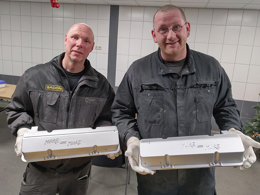
To prevent the covers to oxidate, I had them glass bead polished by Gacon. On the left you see owner Mike Gasseling.

Glass beads polishing seal ’the skin’ of the aluminum so that dirt and oil cannot penetrate.
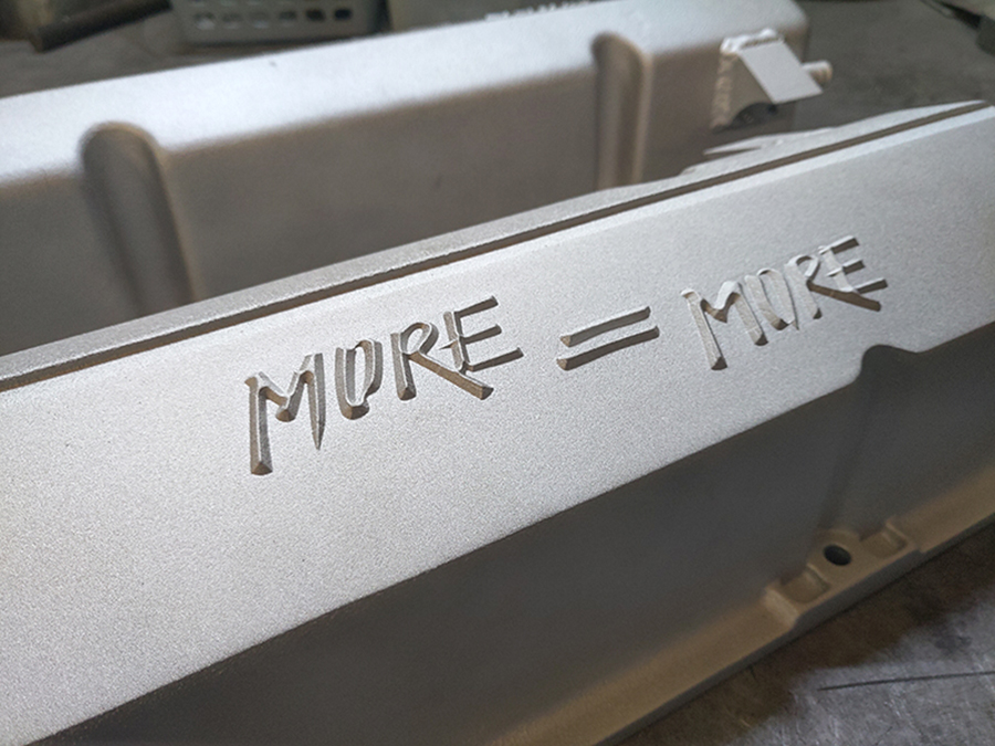
A nice close-up.
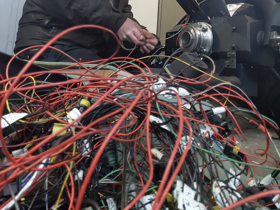
Peter and I wanted to reuse the old wiring: it worked so why not? Well, you can see the ‘why not’ here: a jumble. In addition, we saw that some cables had been pinched during the many splits of the frame, and we suspected that some wires would also have been stretched.
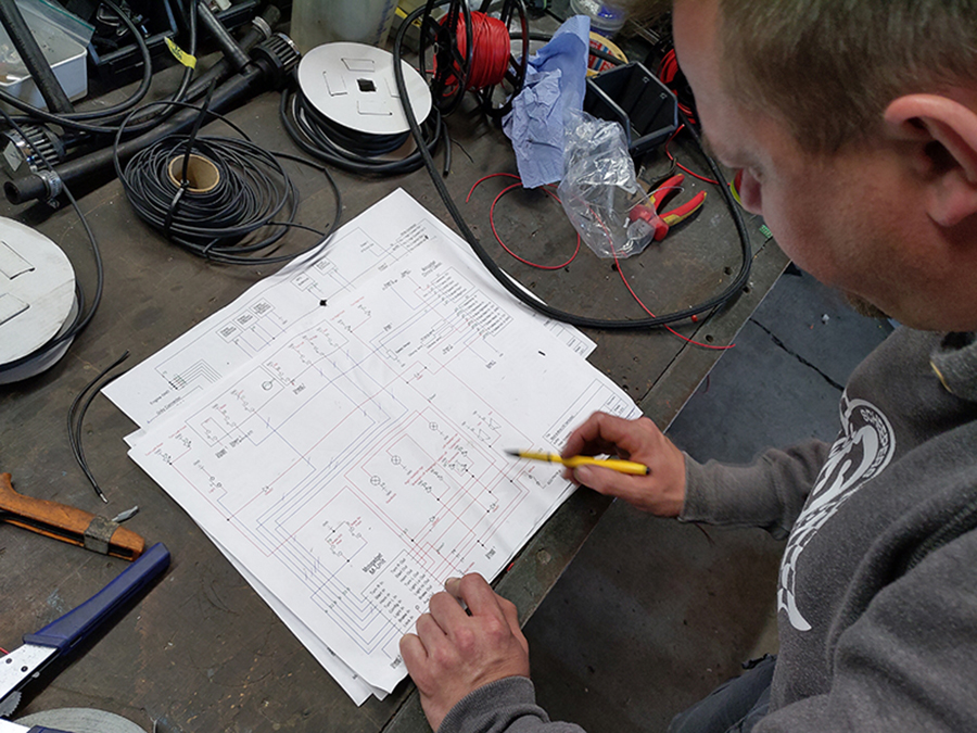
And, since we’d digitally drawn the complete wiring diagram …
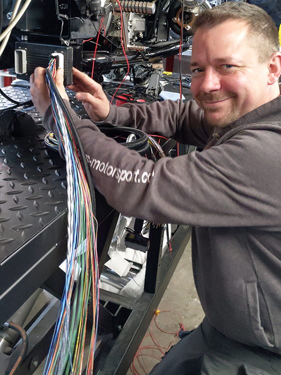 … we decided to put in a completely new wiring harness. Just look at those fresh wires, and that happy look.
 While we were at it, Peter installed the latest version of the digital control box ‘m-Unit’: the ‘mo.unit Blue’, with many new gadgets such as Bluetooth. Sometimes you just have to treat yourself to something. ;)
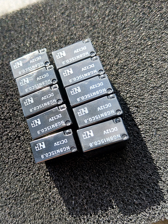 I also had an electronic challenge myself: there was actually too little space for the ten relays in the two frame tubes under the seat. So I went looking for compact relays, and found them in faraway China.

In Adobe Illustrator I drew printed circuit boards (PCB’s) and had them etched by VDR Electronics.
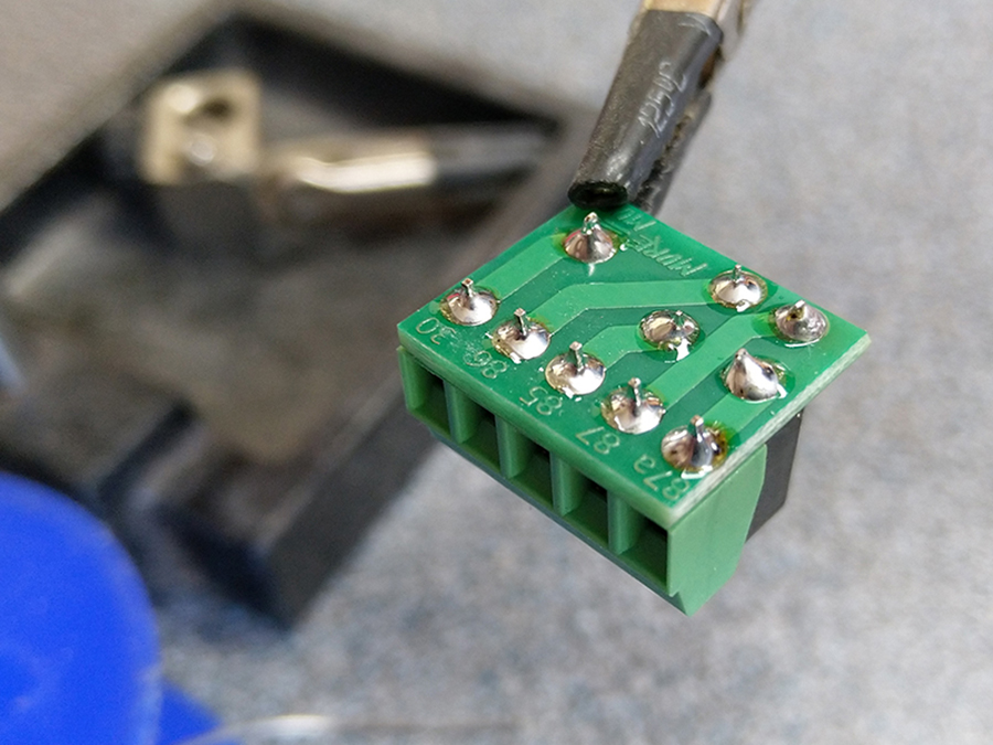
Even the small More = More logo fits.
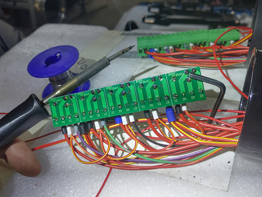
This is what a row of five relays looks like now, taking significantly less space than before.

I designed a compact housing for the relays, and then 3D printed it.
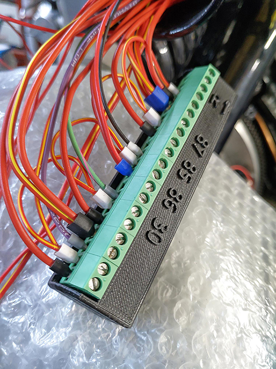 Compact and shielded. This saved space for the many (!) wires, and for the rear lights.
And so we arrive at the paintjob, of course a decisive phase for the appearance of the bike. Concept: coarse matt black combined with high-gloss black. Fortunately, painter Bart Colenbrander, aka Kustombart, likes a challenge because that’s what it was. Just like everything else in this project, but you know that by now.The video gives an impression of the coarse matt – gloss contrast.
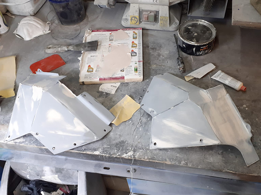
A car with a trailer filled with sheet metal headed for Apeldoorn. For Bart, it meant weeks of sanding, filling, masking and spraying …

… in large ánd small.
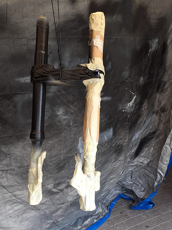 Installing the triple tree turned damaged the paint on the fork legs. So I delivered them as a whole, as you may have seen in the previous photo.
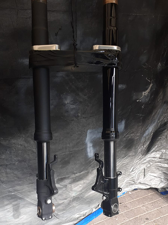 Coarse matte on the left, glossy on the right.

Curved surfaces, such as the headlights here, required some consultation via WhatsApp. That went smoothly.
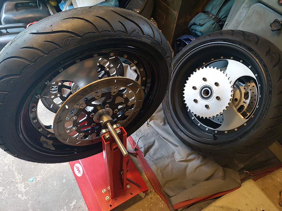
 Things didn’t work out so well with the inner surfaced of the rims. I removed the tires, split the rims …
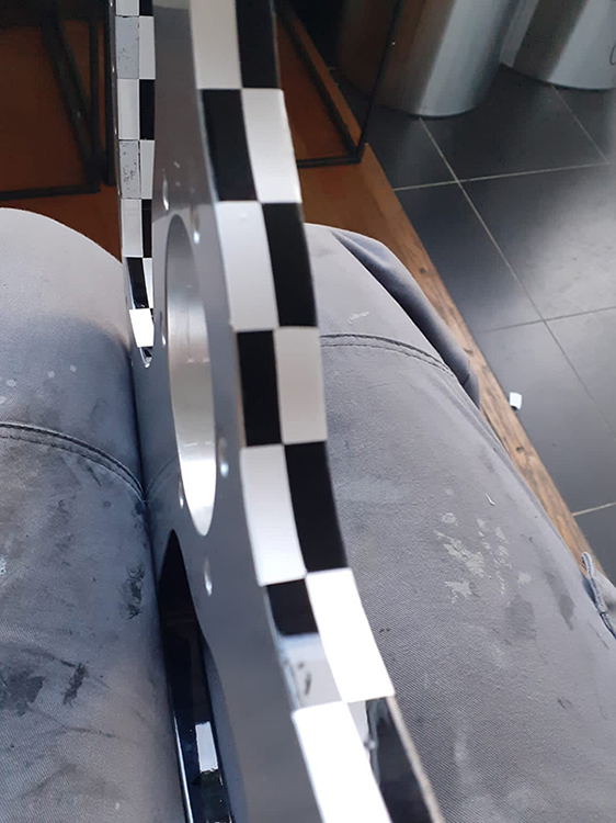
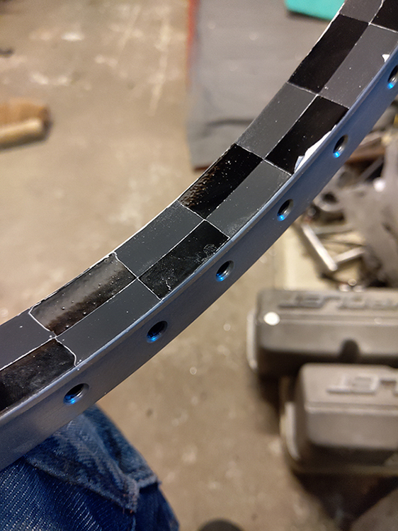 … but the block pattern was as wanted.
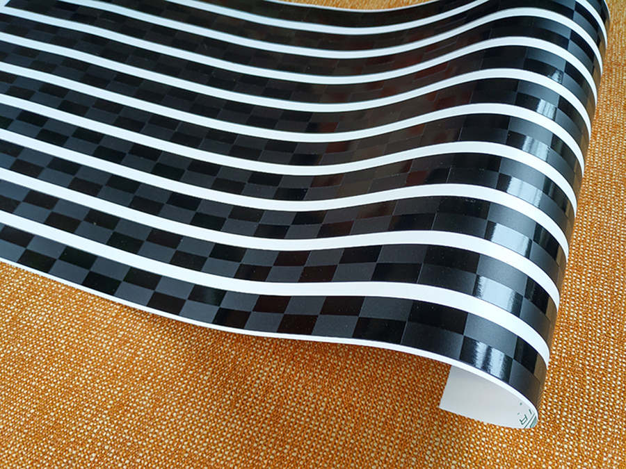
So I drew the pattern in Illustrator and had the foil printed at blackfishgraphics.com.

Et voilà!
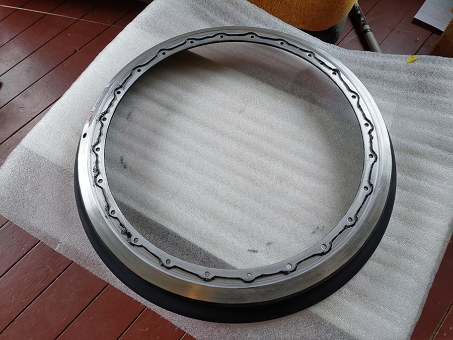
With special rim kit I mounted the three rim parts back together …

… with a torque wrench, of course, so that each bolt is tightened with the correct torque. The bank card and the masking tape prevented scratches on the paintwork.
Re-building the bike as scratch-free as possible is a very delicate job and therefore takes a lot of time.
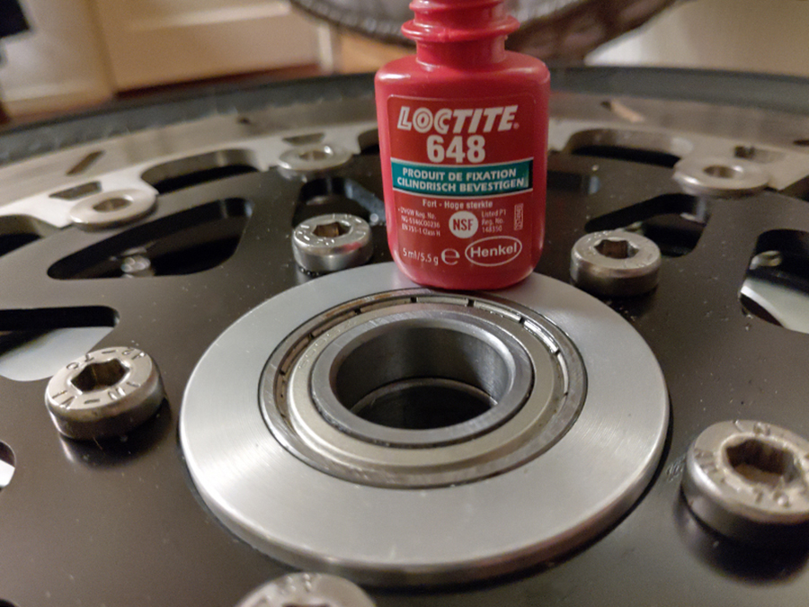
Four new bearings in the front wheel and four in the rear wheel …
… and the tire back on. That was easier said than done, unfortunately.
Kwikfit Nijmegen apparently had new staff who couldn’t get my brand new rear tire on, and even wrecked it with 8 (!) bar pressure. Fortunately, Theo Janssen then took the time to professionally put a new one on.
Again I balanced the wheels, in peace.

Black rims and then metal colored balancing weights? Of course that’s a no-go. Fortunately, there are black ones on the market.
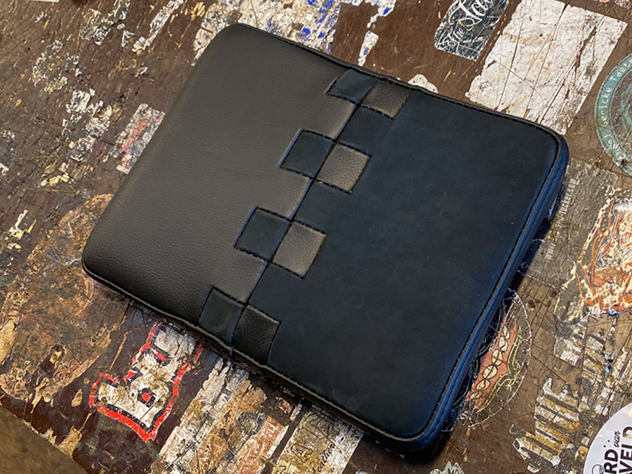
I also wanted the matte-gloss contrast on the seat. An experiment with stitching did not look good.

I do a lot of lasercutting but didn’t know you can ingrave leather with it. This makes the lether matte, and that was the solution. The stitching was done by Miller Kustom Upholstery.

That’s all, in almost three years? No, of course not! :)
I left out the terrible Dyno test day March 10, 2021 (want to forget that day), lost notes, (ouch), trouble with the batteries and the demise of my favorite parts supplier Technisch Bureau Holl.

And now? Continue with finishing wiring, testing electronics, engine start, paintwork. Quite a lot.
Also installed a new and important sensor, near the camshaft, so that the engine can now be injected sequentially. As a result, the amount of injected petrol can be selected per cylinder per speed, which will have a positive effect on the power.

Twelve updates … twenty years of building … all I can say: until the next one! ;)