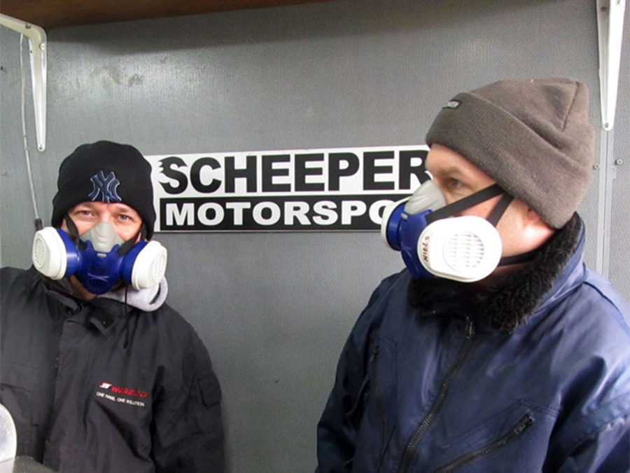
February 13, 2016: positive thoughts on what could be our final testing day. With a little bit of luck the V8 would show its real potential. Followed by disassembling, paintjob and hitting the road.
To favor the gods, I’d purchased three professional gas masks, partly because today the water-methanol system would be used. And that’s harmful stuff.
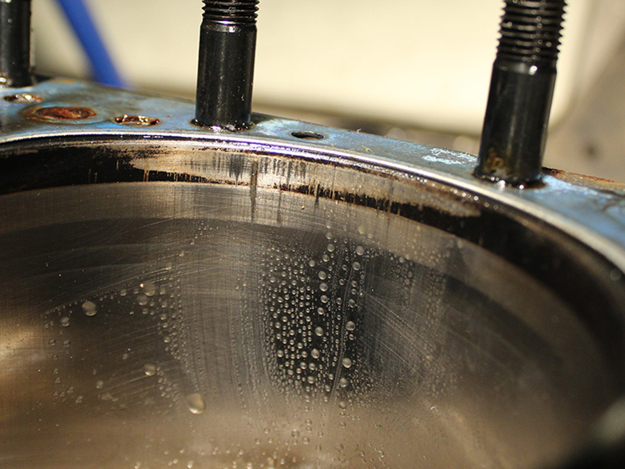
Unfortunately: no way. The oil level was too high and cloudy. So we heated up the engine, drained the oil, replaced the oil filter, and put fresh oil in. There appeared to be coolant in the oil, and that’s not a good sign at all.

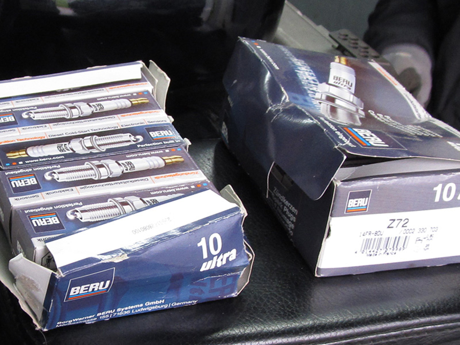
The exhaust gas measurements showed major differences between the left and right cylinder bank, and that’s no good. We replaced the spark plugs. After a big blue smoke plume we stopped testing; something’s not right here. And even a bit more than something.
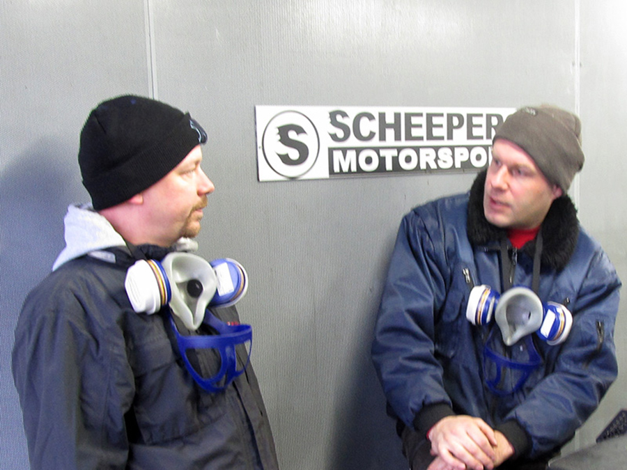
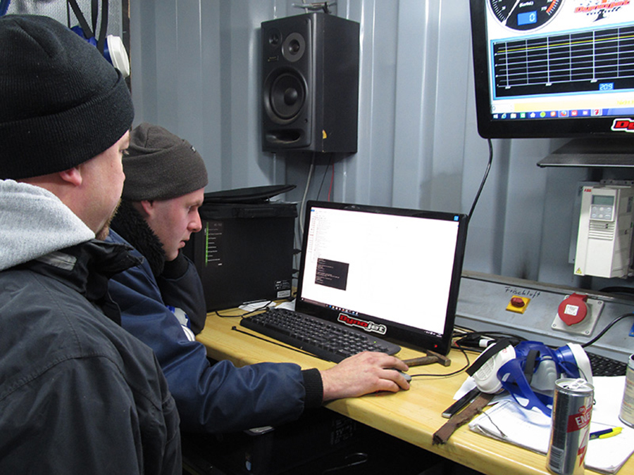
and analysed the test results.

Tja. De motor bleek ziek. Verder testen had geen zin.
Well. The engine was sick. Further testing didn’t make sense.
We drew the following conclusions:
1. The cause of the coolant leakage must be found and remedied.
2. The engine does not get enough air because the flow of the intake manifold is not good. Not enough air means not enough gas means not enough power. And 350 rear wheel hp is not enough power, that’s very clear.
So what do you do? You disassemble the whole bunch. More then ever before.
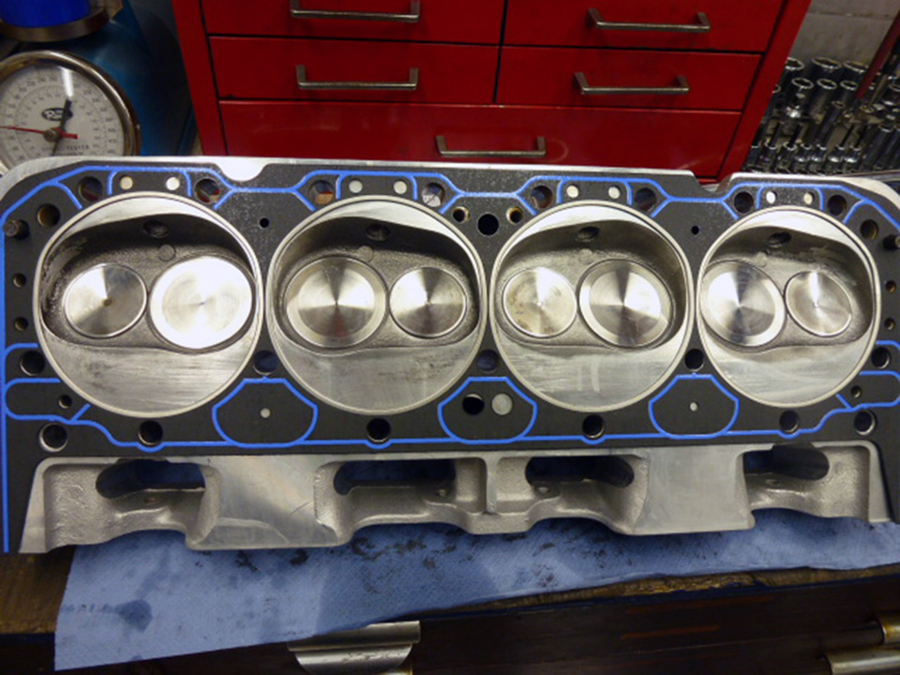
The coolant leakage was partly due to the fact that the 2K filler I used was not glycol resistant (see update #8), and partly that the intake gasked was too rigid for my aluminum intake manifold. Now that I switch from FelPro # 90314-2 (‘Standard’) to FelPro # 1205 (‘Performance’) that problem is probably fixed.
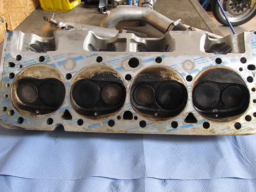
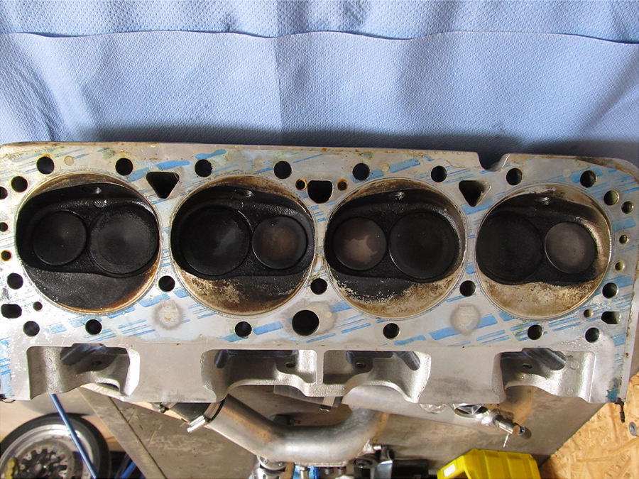
The heads clearly showed that the air flow in the intake manifold was far from ideal. From left to right you see the valves and the combustion chamber getting more and more black: on the left, where the air enters, the air-gasoline mixture is too lean, so little carbon but temperaturs too high.
On the right, at the back of the manifold, the air-gasoline mixture is too rich: cooler but much more carbon deposit.
And in between it’s good. More or less. So: not good at all.

That same month Michel Verrips (r) visited the scene of the crime. He has a lot of experience in engine tuning, especially in designing intake manifolds.
The challange is getting as much air flow as possible in the limited space between engine and tank.
This is what the original intake manifold looked like, just before it was welded (long ago). The square tubing provided a bad flow. ‘No worries’, I was told ten years ago, ‘your huge turbos will press the air wherever it has to go, no matter size or design of the manifold.’ This turned out to be true, but no further than 350 hp. And we want to get past that, and a lot.
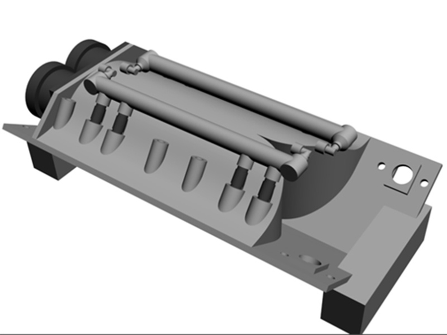
The new manifold is clearly more voluminous.
The eight lower tubes (four of them visible here) hold the injectors, the six higher tubes (here three visible) will bolt the manifold on the cylinder heads.

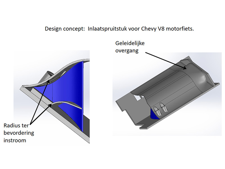
A look inside the new manifold.
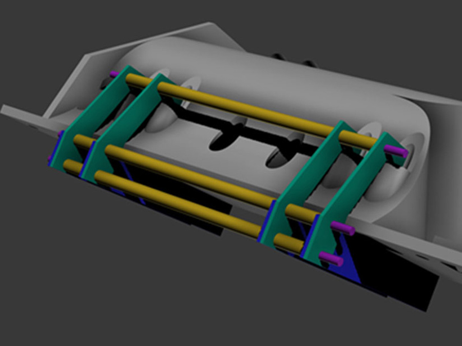
The interior contains ten bent dividing walls to guide the air into the cylinders.
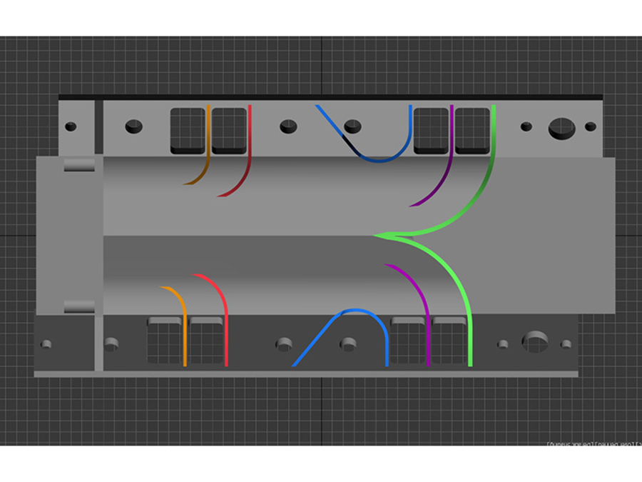
In this drawing the walls are colored.

The colored dividing walls as seen from the throttle body, at the front of the engine.
 I came in contact with Peter Schneider: he installs and repairs professional 3D printers. We discussed the possibilities to print my new intake manifold instead of constructing it. This would save a lot time: directly from computer model to end product. No welding and therefore no deformation due to the input of heat. Sounds ideal.

Peter owns a 3DSystems printer, which operates to the so-called SLS principle: Selective Laser Sintering. Layers of 0.1mm very fine plastic powder are stacked.

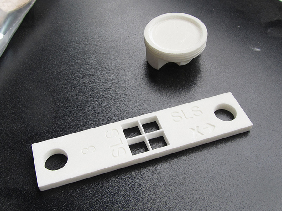
Once the lasering is ready, the powder package must cool down slowly and the parts can be taken out. These can be simple products …
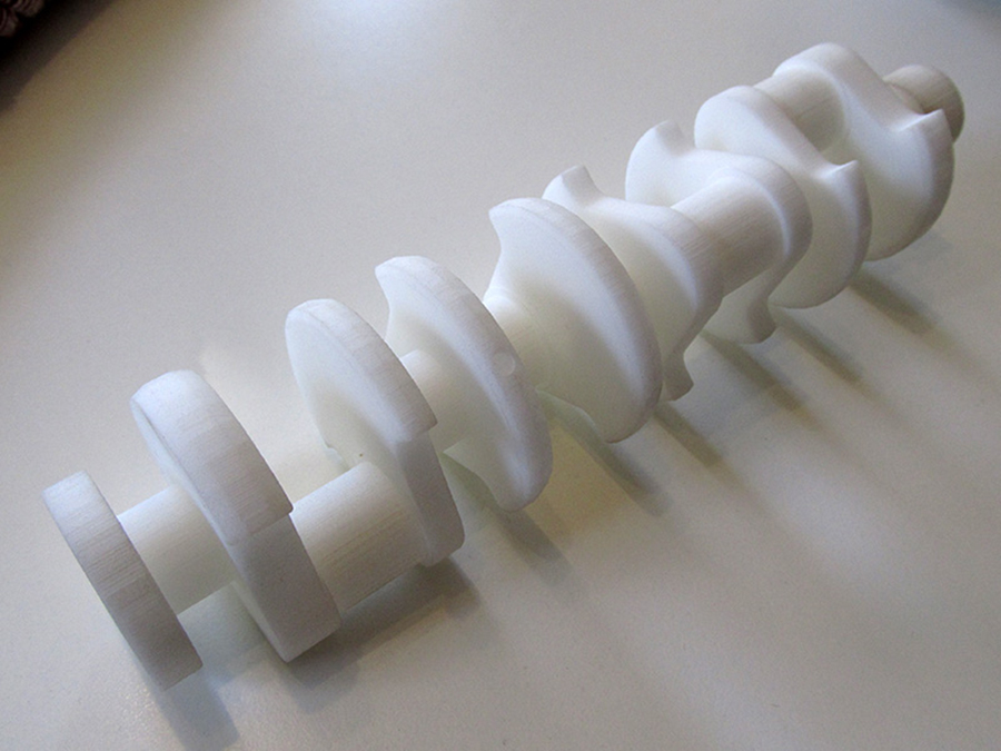
… but also complex ones, like this crankshaft.
Unfortunately, there was too much uncertainty about strength, shrinkage, gasoline-, oil-, coolant- and pressure resistance of the available plastics.
Nowadays printing (‘sintering’) in aluminum and stainless steel is also possible, but not with Peters printer. And they are a bit ‘above budget’: 8,000 (aluminum) and 30,000 Euro (stainless steel). All in all too risky and far too expensive. But this technique is, of course, the future.
 I then printed a prototype with the Ultimaker 2 Extended. This is a so-called Fused Deposition Modeling (FDM) printer that costs only half a percent of Peter Schneider’s SLS printer. My friendly and skilled colleague Paul Spannenberg operates this machine.
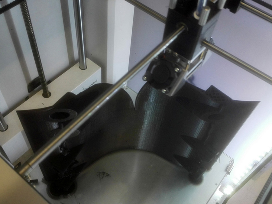
The printer works like a kind of glue gun that stacks thin layers of plastic (eg nylon). The whole manifold was printed in eight parts; this took a few hundred (!) hours, making it the biggest printing project of the academy until then.

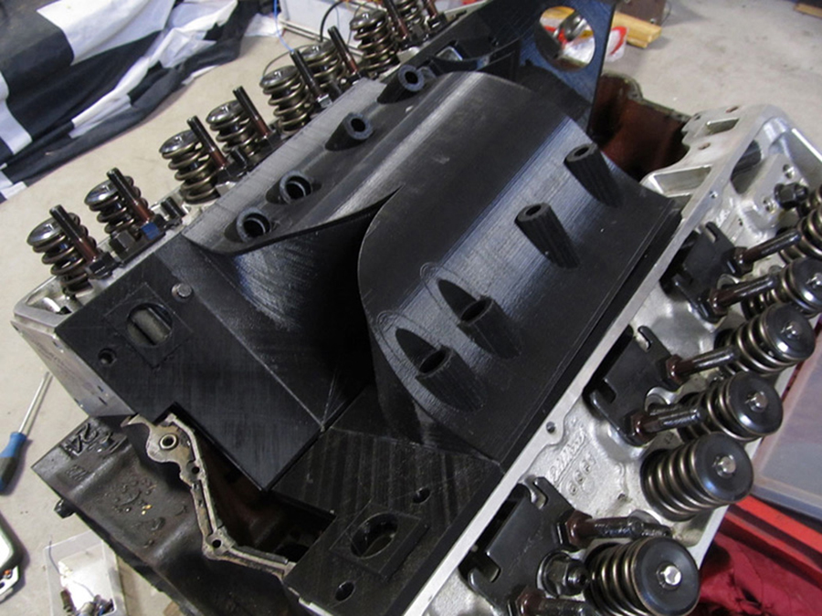
Fitting segment after segment on the engine.
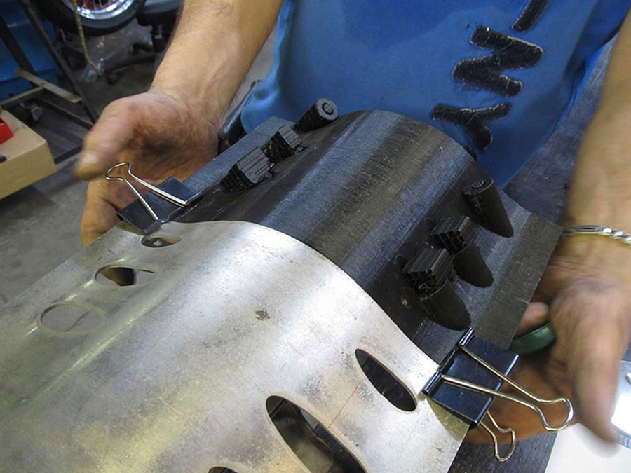
So aluminum it was, the old skool way. I had the parts watercut and used the 3D prints as shape indicators.
It was very pleasant working with Dirk and Hans at this DIY-kit. It took us about 50 hours to complete the manifold. Quite a big job, like everything on this bike.

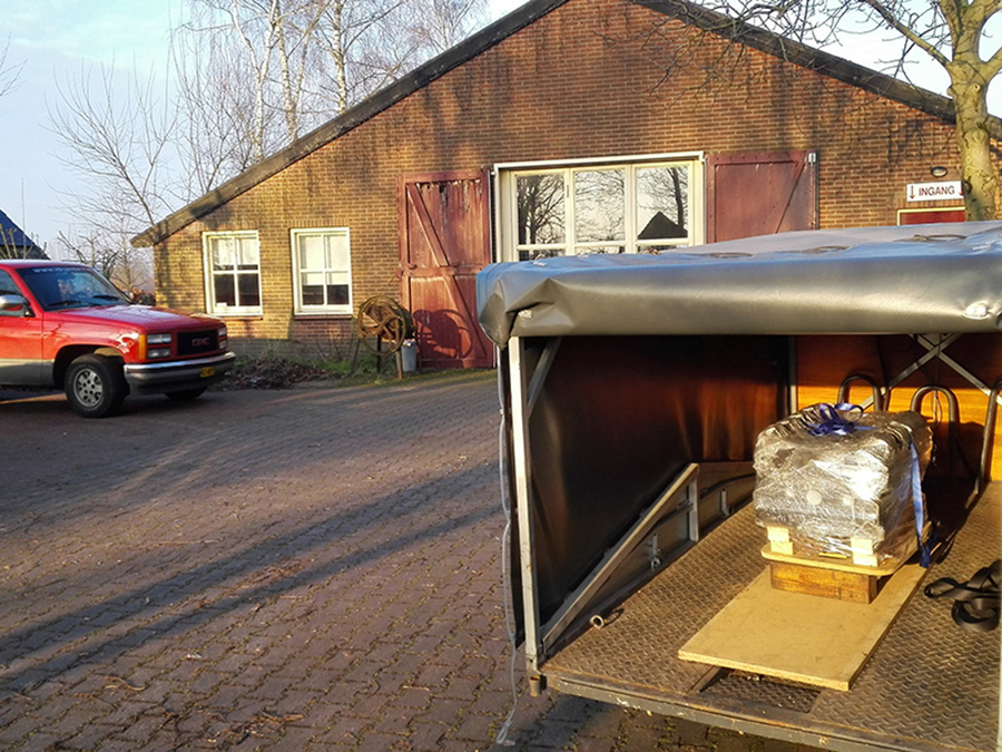
We worked in the Netherlands and in Germany. Which sometimes led to rather unconventional transport of tools (like this 20L Argon cylinder) between the two countries.
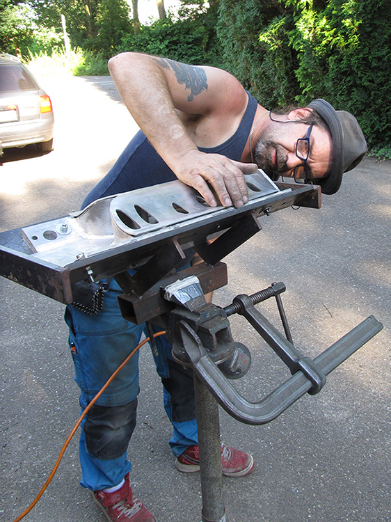 Dirk as Master of Modeling …
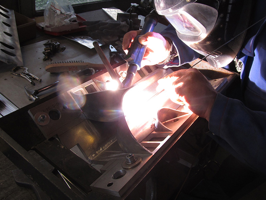
 and Hans as Master of Welding.
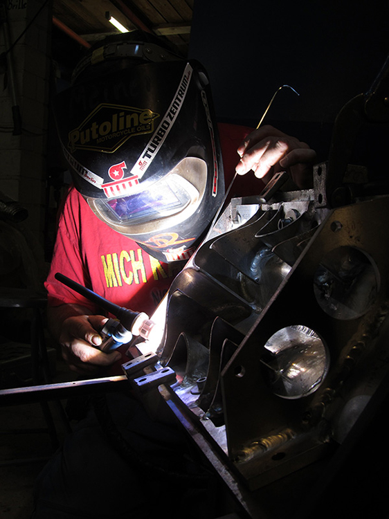 More than once we burned the midnight oil.
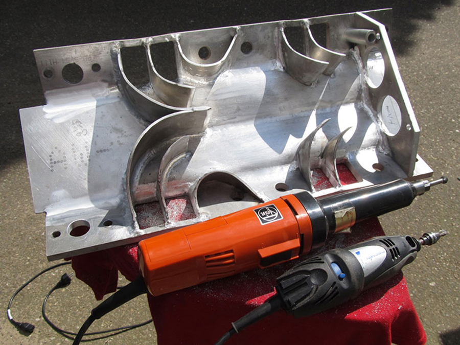
Any unevenness on the inside causes unwanted air swirls. It took me two days, as Master of Grinding, to finish the inside.

A lot of precise work on the lathe, like this injector fitting.

Conventional machining, I love it.
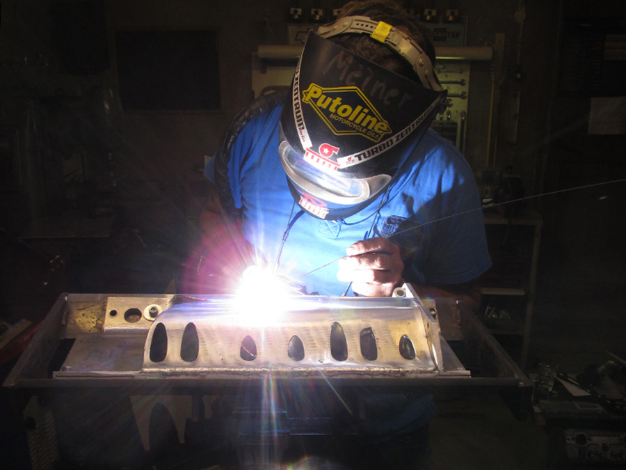
Welding the cover.
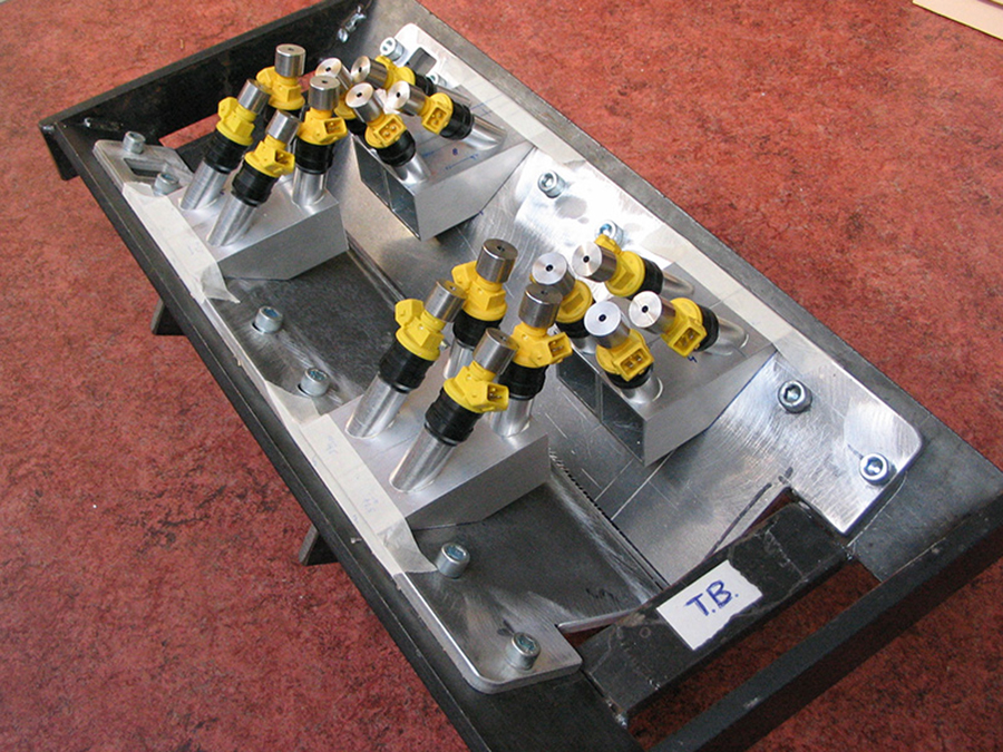
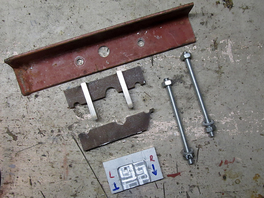
I designed a construction to ensure the injectors being exactly in the right spot. The parts were watercut.
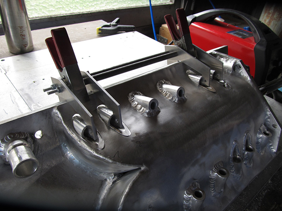
That worked just fine.
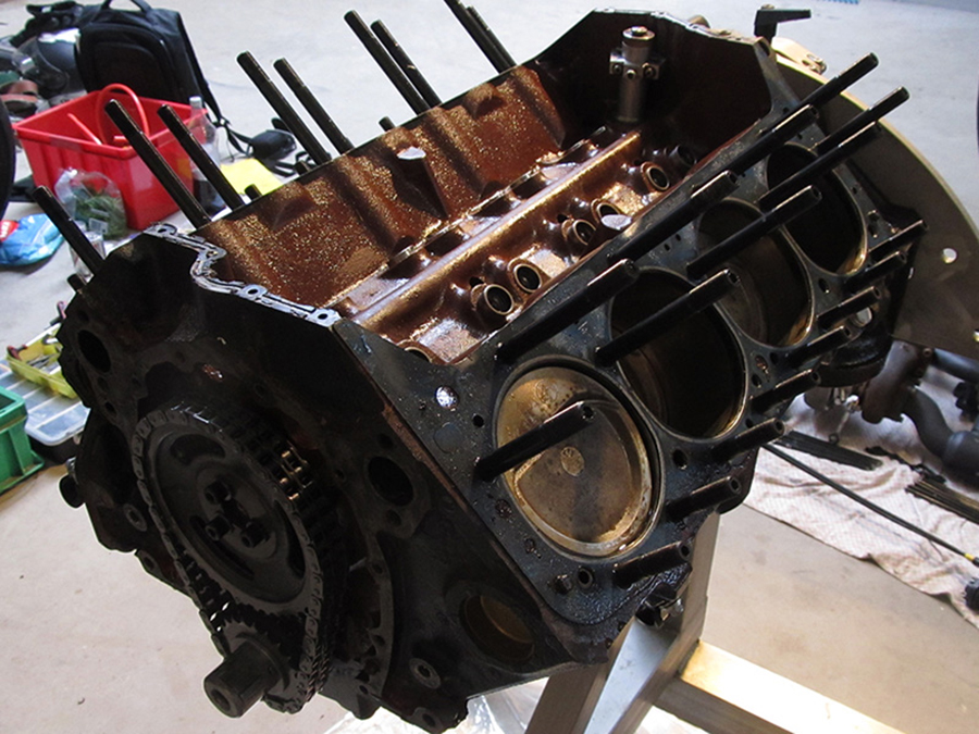
I prayed that the rest of the engine was salvable. That wasn’t the case: a complete overhaul was inevitable. The coolant had pushed away the oil film of all the rotating parts, so metal scratched on metal.
German V8 expert Jürgen examined the patient. He promised to make a quote but ended up with a lot of lame excuses. In Germany they call that ‘Zeitverschwendung’…

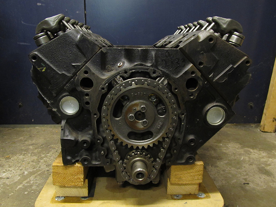
Ronnie Spijker guided me to Jacco Griekspoor. His company, Jacco Cars & Parts (“no website, don’t need one”) is all about overhauling US engines. We immediately had a connection: V8, but also six-cylinder bikes (he Kawa, me Honda), and Münch Mammut. My engine would be in good hands.
His workshop is as clean as an operating room and provides everything that a overhaul heart desires.
Sadly not even overhauling was possible: unfortunately the engine could not be saved. Some cylinder walls were so scratched that the wall thickness would be unacceptably thin with oversized pistons.
Talking about ‘unfortunately’: the crankshaft couldn’t be saved either. And Jacco advised other (heavier) connecting rods. And yes, while we’re at it, let’s put a more aggressive camshaft in. A serious upgrade, and financial a very painful one.
Jacco found a high performance fourbolt engine, with nodular iron (thus stronger) crankshaft caps.
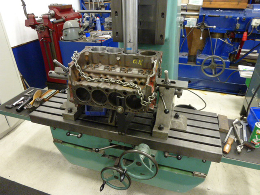
Here the cylinders are rebored.
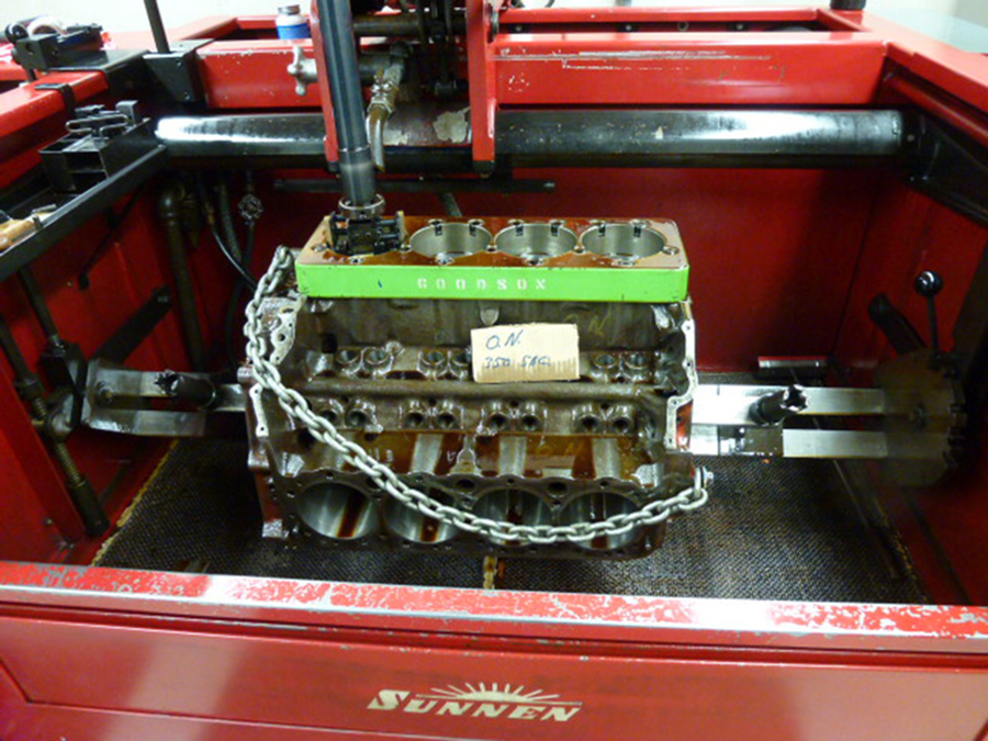
A heavy pressure plate is bolted to the engine before the cylinders were honed.
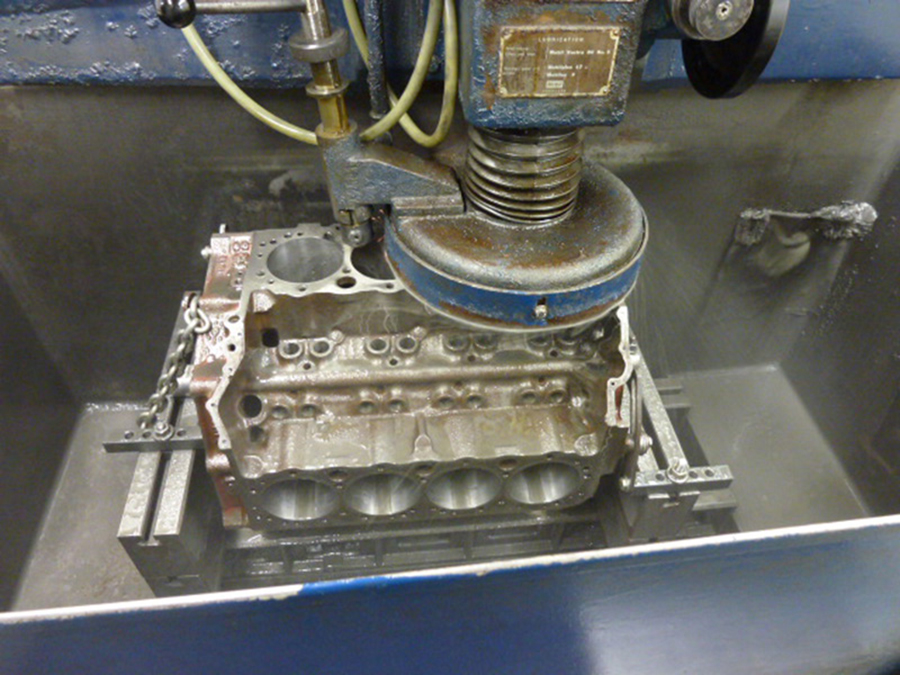
The heads being flattened.
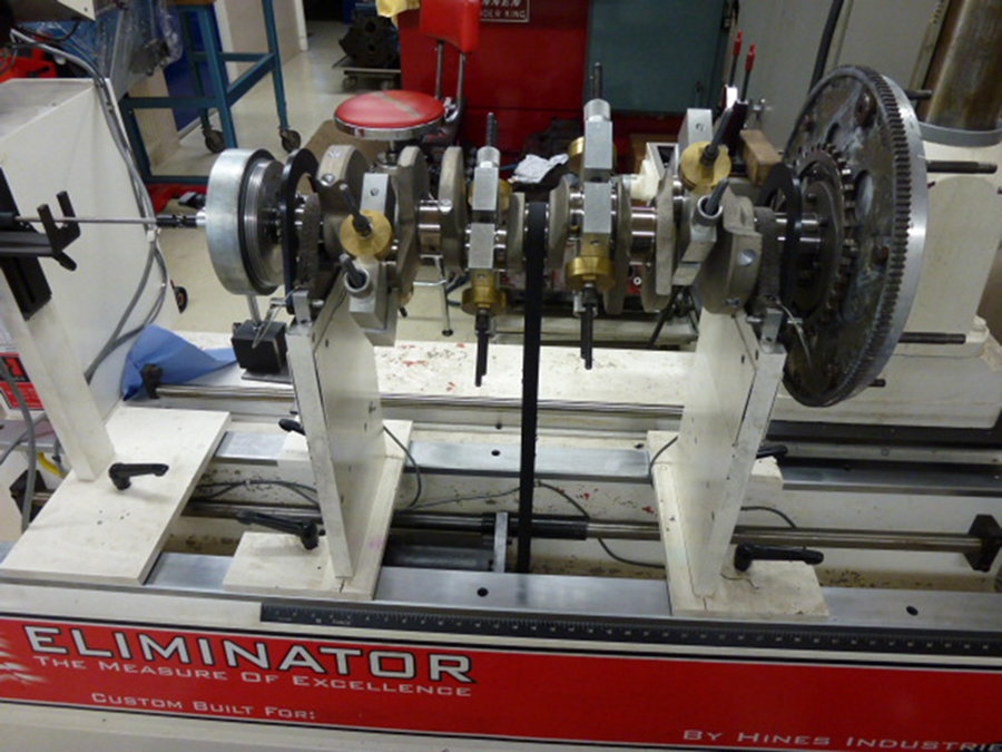
The new high performance Eagle crankshaft is balanced with balancer (l) en clutch (r).
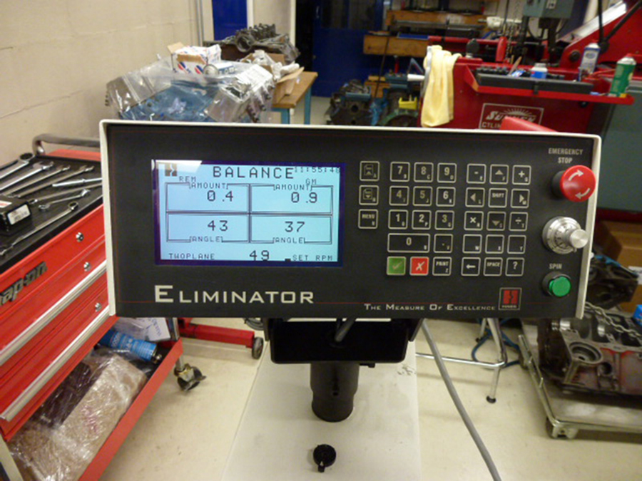
This is all very delicate: a poorly balanced engine greatly increases internal wear and is very dangerous, especially in a motorcycle.

The aluminum heads were also thoroughly treated; here the valves are grinded.

After that they look like this.

The valve seats were grinded as well.
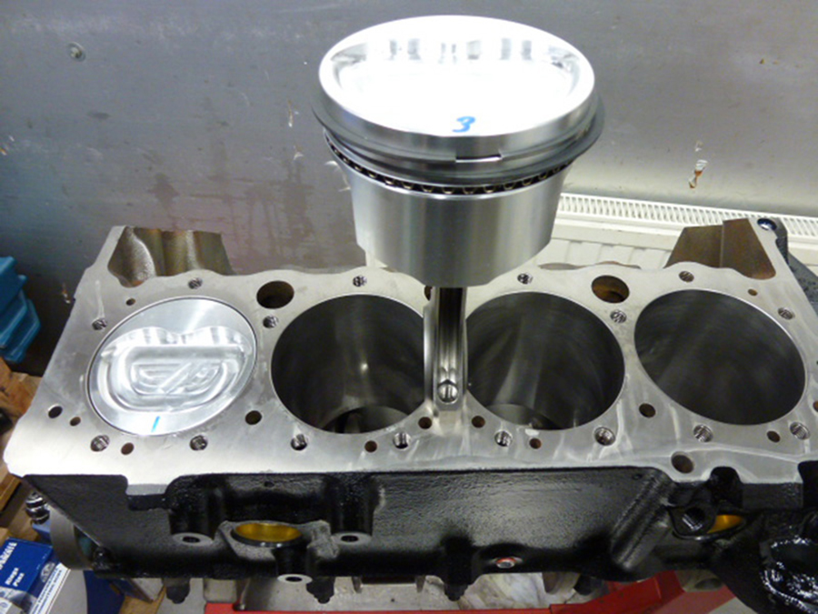
New dished pistons, and new pushrods.
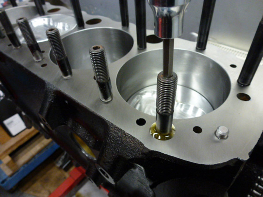
New studs.
The heads before Jacco …
… and after Jacco.

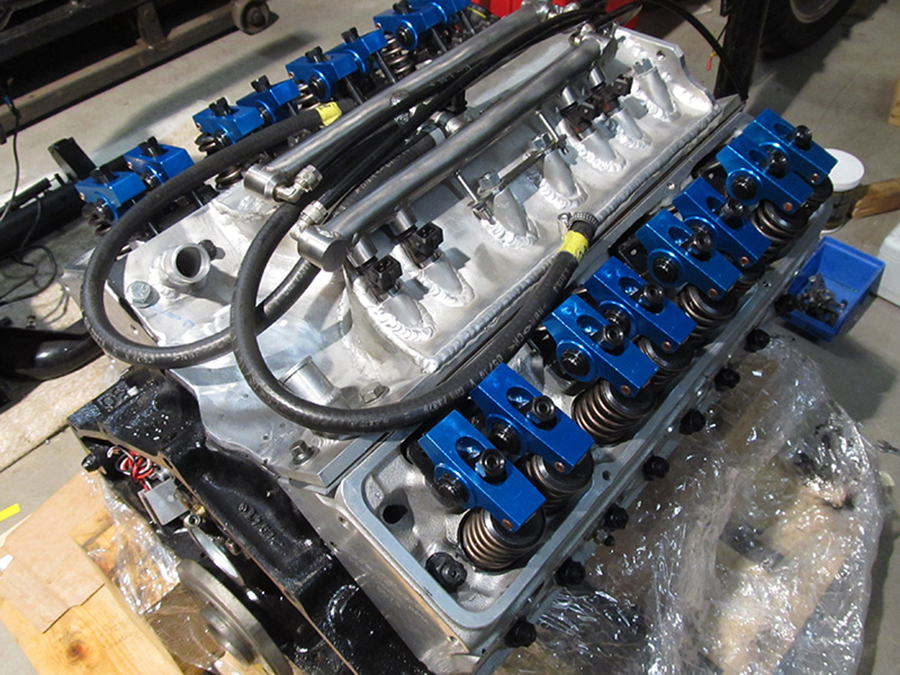
The roller-rocker arms (blue, on top) were inspected and, where needed, modified.
And, of course, new bearings, valve stem seals, oil pump and gaskets.
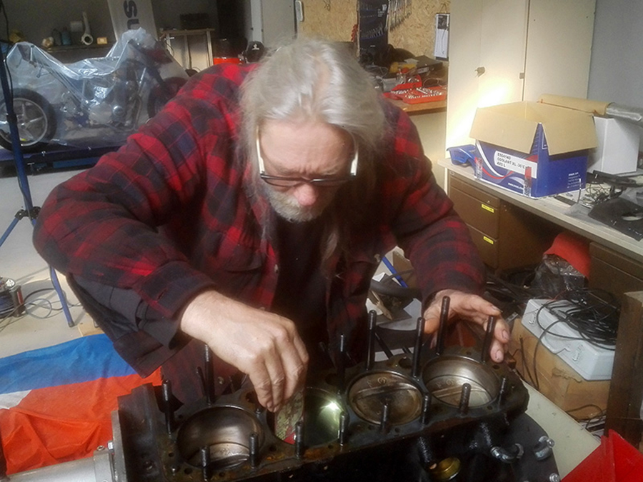
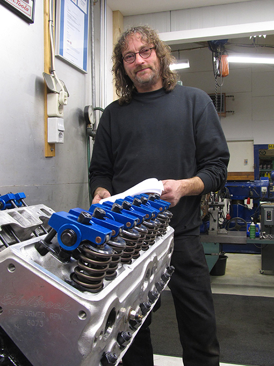 This picture is called ‘Portrait with Engine and Modest Overhauler’, and is for sale. ;)
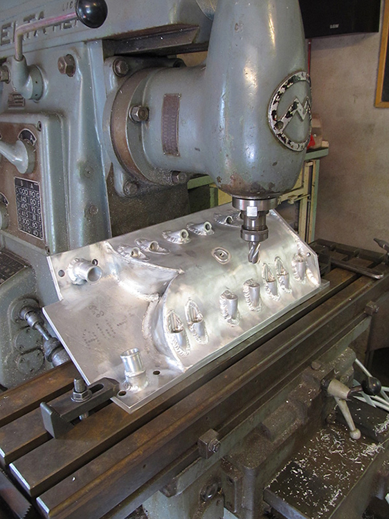 Meanwhile, I finished the exterior of the new manifold. And in the middle of doing that …
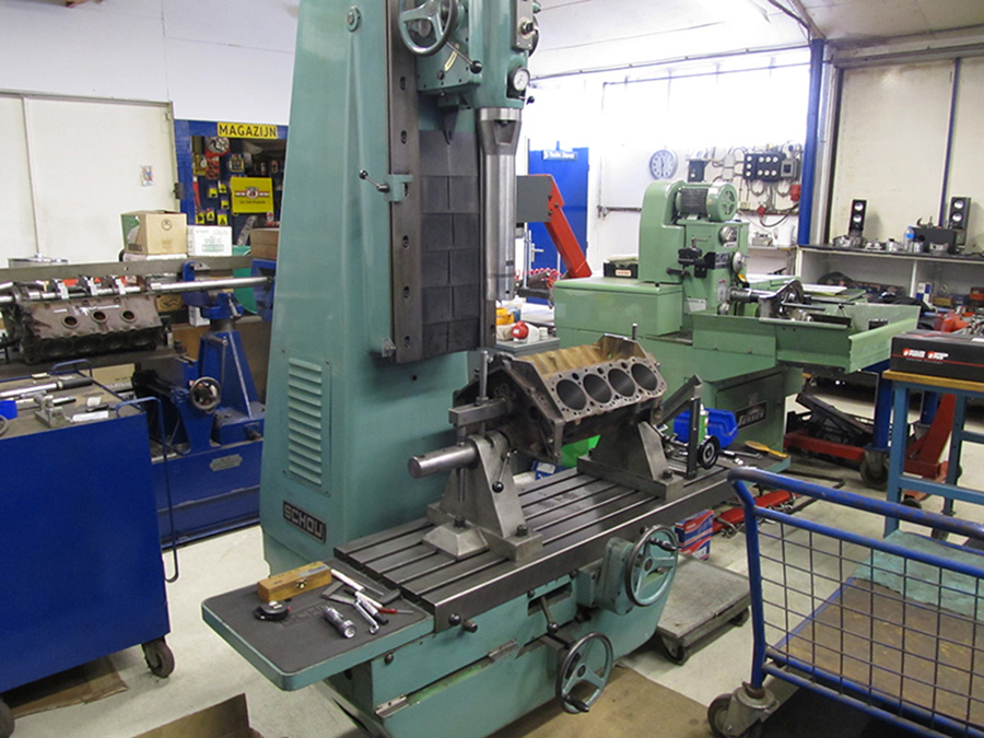
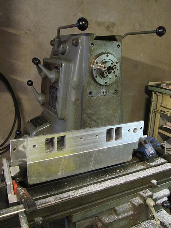 … my loyal mill quit. Fortunately, I could dismantle and repair it myself.
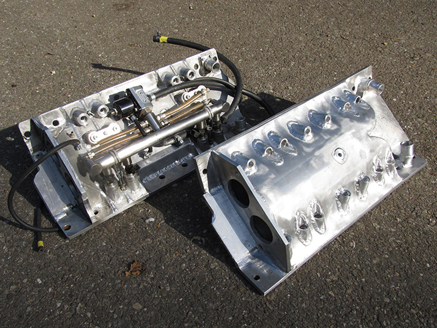
On the left you see the old manifold, on the right the new (and significant bigger) one.
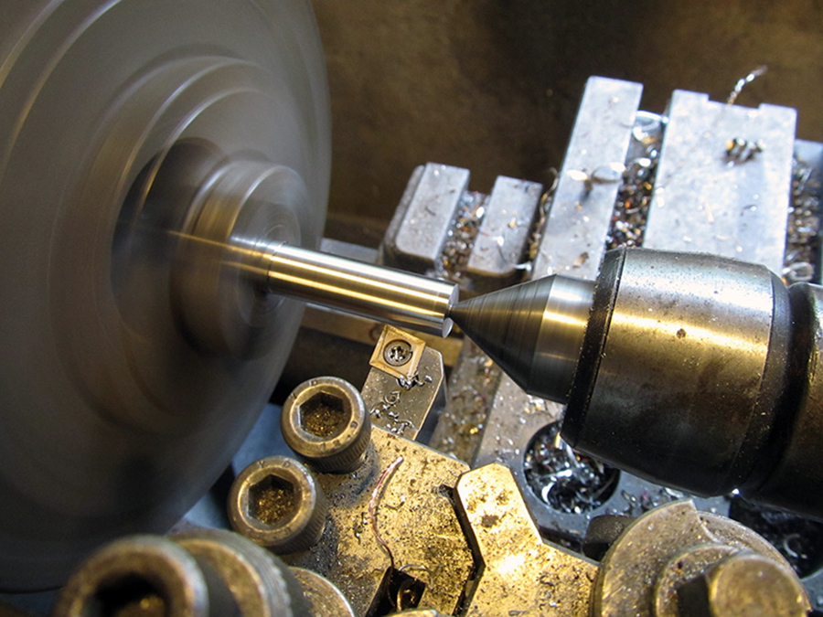
From a stainless steel bar …

… I lathed a hose pillar …
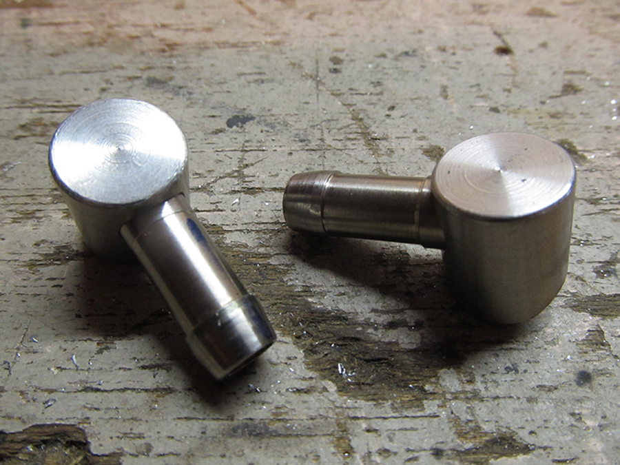
… made it angular …
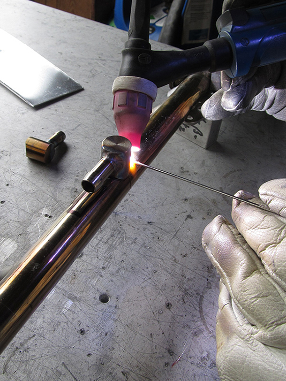 … and Hans welded it on the new fuelrails.
That starts to look like it.
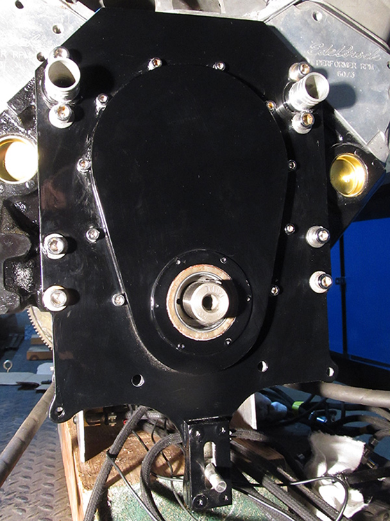 Rebuilding is always rewarding. Here you see the nice painted front plate (by KustomBart).
Less satisfying is that, apart from this plate, the looks of the bike didn’t change a bit. And at the same time that was my intention. Are you still with me? :)
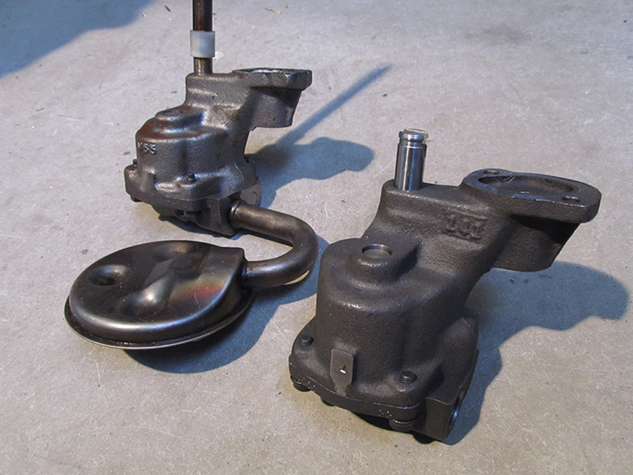
Nothing is for free in this project: the ‘old’ oil pump (left) was quite smaller than the (of course: more powerful) new one.
To press the oil screen into the pump, I built a one-off construction.
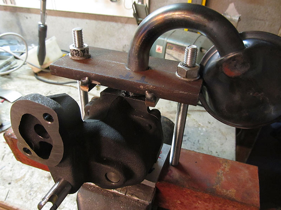
Quite a lot of work for just one act.
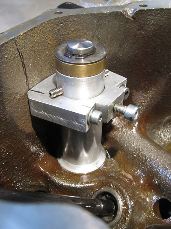 The new engine was slightly different from the old one. Almost everything, like my oil pump drive, had to be modified.

There was no space left on top of the new intake manifold for the fuel pressure regulator. It had to move it to the front of the bike, just behind the steeing-head tube.
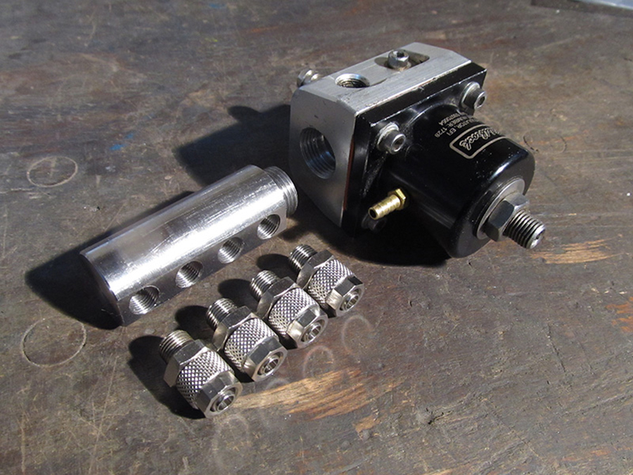
And modify it, of course.
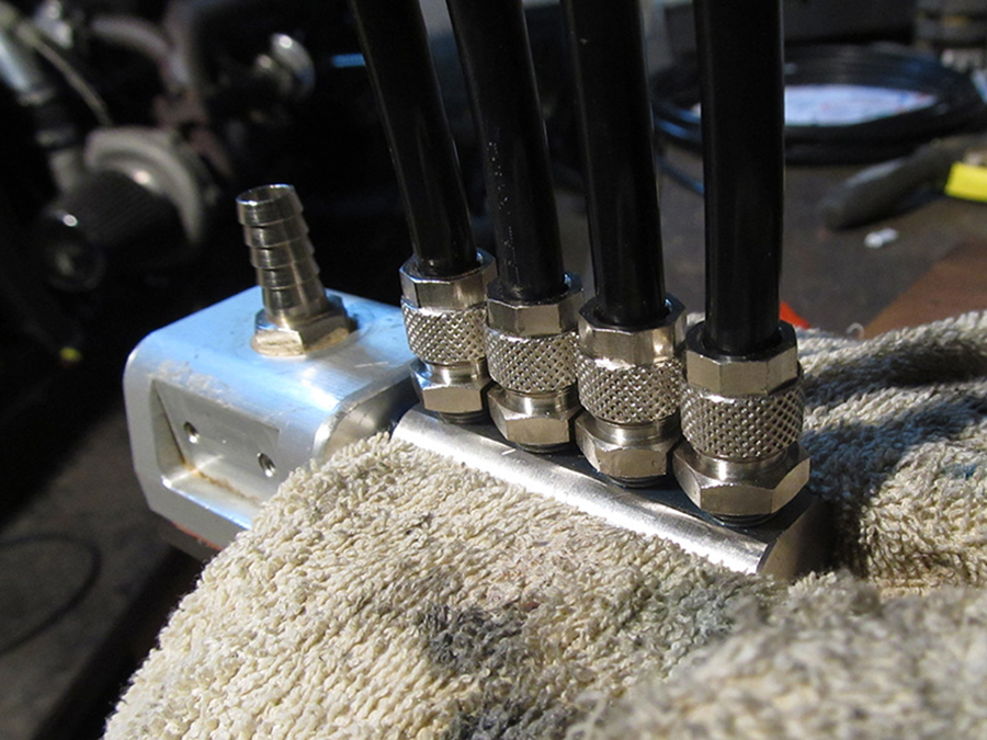
Four fuel lines, snug side by side.

In each of the eight exhaust tubes I drilled a hole for a so-called EGT (Exhaust Gas Temperature) connection. There will be eight new temperature sensors: the exhaust gas temperature gives important information about the combustion (too rich, too poor or good), and that of course it is of the utmost importance for engine tuning.

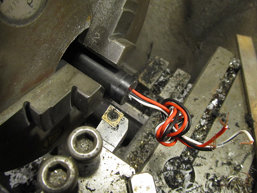
Even the sensor had to be modified.
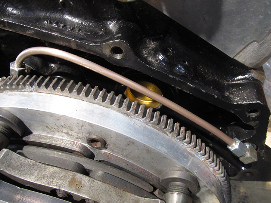
Also on the back of the engine: a new oil line for the oil pressure sensor.
 Always a nice activity: problem solving at Holl, this time with Remco.
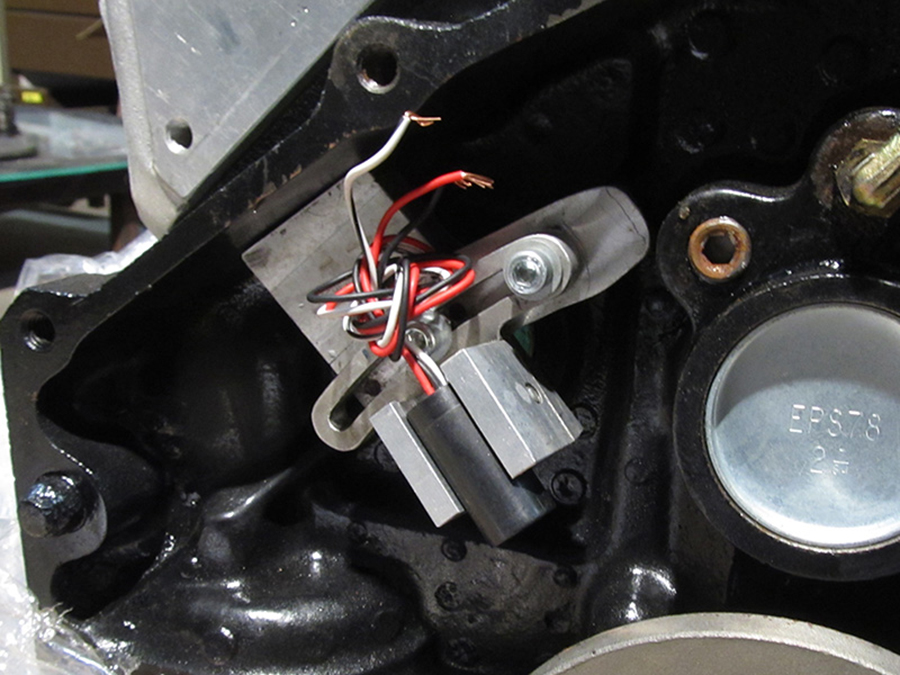
And yes, the sensor grip also needed modification.

And then, last but certainly not least, we come to the electronics. The MS1 controller (left), the brains of the bike for ten years, has done a very good job. Peter convinced me that this is the time to switch to MS3Pro. Again it costed me an arm and a leg.
In order not to go completely bankrupt, I had to sell my first engine.
I made a great deal with Kevin from KB USA Parts: he checked the engine and resold it to a customer. Everybody happy.
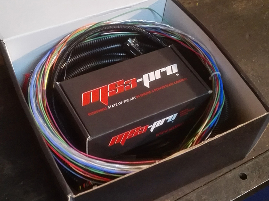
Back to the electronics: the MS3Pro.
Its benefits are almost too many to mention. That said, here are a few of them: waterproof, vibration-proof, sequential injection, stepless water-methanol injection, traction control.

Via Skype, Niels (top left), Peter (top right) and I (left bottom) discussed the options, and drew a wiring scheme (bottom right) on the spot.
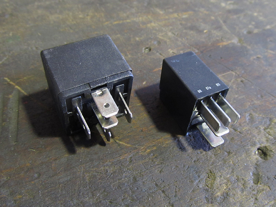
Other electronic components will also be replaced: the new relays are only half the size of the old ones.
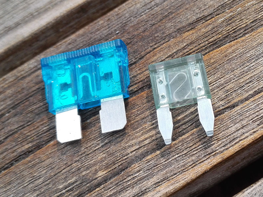
The same goes for the fuses.

The original oil pressure sensor also had to leave the battleground: the new one on the right is identical except for an additional connection.
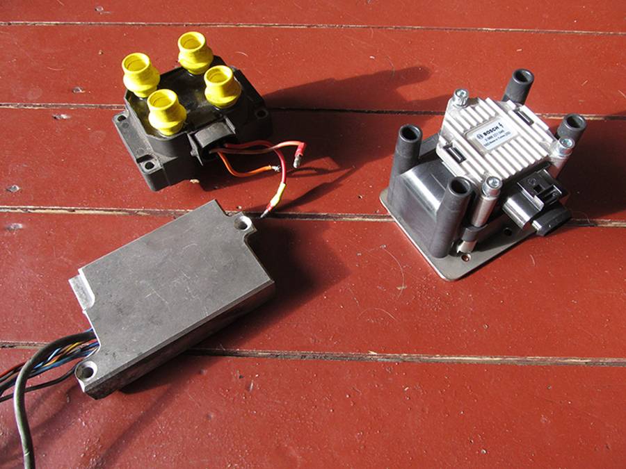
And the coils will be replaced too: the new version (right) has the same functionality as the left coil including the external EDIS module. Electronics versus microelectronics.
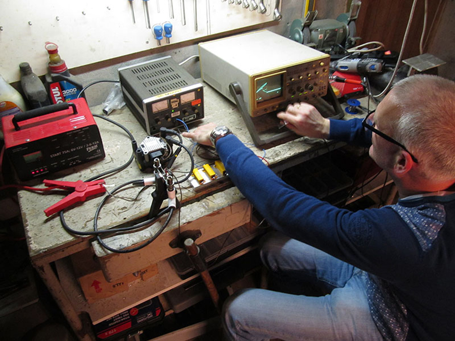
 We got the test setup working, and that resulted in beautiful sparkling spark plugs. Better don’t touch:
± 20,000 Volt discharges.

Last month the wiring phase started: the old cable harness will be completely (!) replaced by Peter. A major job in which concentration is essential.
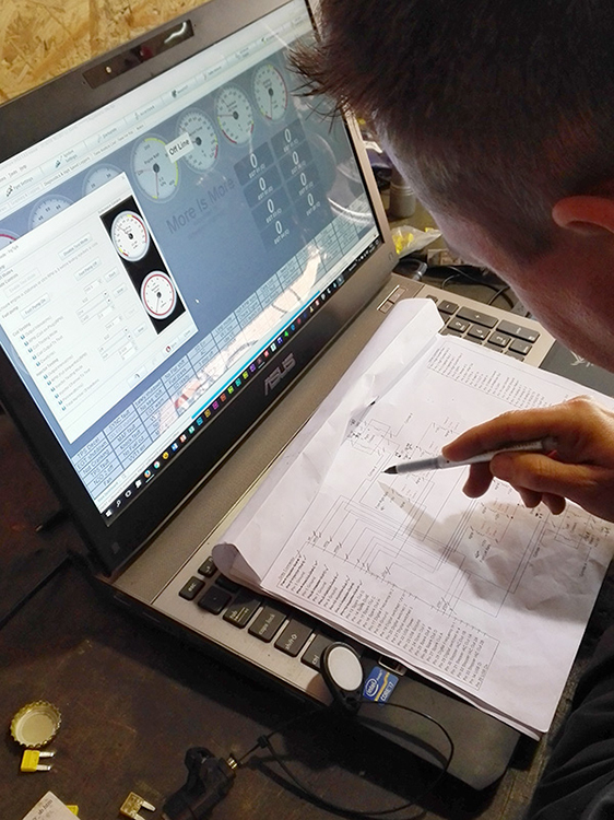 Important to take time updating the wiring diagram. We’re making good progress: the electronics are tested thoroughly before the engine will make its first stroke. As we speak, all wiring has been laid and many features have been checked: the brain is alive!
 And that is fun. As you can see.
“Okay, and now what?”
– “A bit of wiring, a bit of Dyno testing, a box of spray cans, that’s all.”
“Really…?”
– “No, of course not!”
See you next year! … here :)